
Specifications

6
CYCLE TO EPAP
END EXPIRATION
ADDITIONAL
LEAK
NEW BASELINE
ORIGINAL
BASELINE
INSPIRATION
5.0 SECONDS
Adjustment of
Spontaneous Trigger
(V
leak
)
(V
leak
)
TOTAL FLOW
(V
tot
)
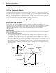
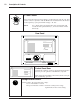
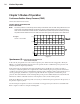
Figure 3: Expiratory Flow Rate Adjustment
3.2 Flow Sensing and Analysis
A flow transducer derives a signal proportional to the Total Flow Rate (V
tot
) in the patient circuit. From
this signal, the system calculates the component of flow, known as the Estimated Patient Flow Rate (V
est
),
as well as the component derived from leaks in the patient circuit, known as the Estimated Leak Flow
Rate (V
leak
). Patient circuit leaks are composed of flow through the continuous flow exhalation port as
well as any unintentional leaks that may be present around the interface seal.
V
tot
= V
est
+ V
leak
Principles of Operation
BiPAP
®
Auto-Trak Sensitivity
™
An important characteristic of the BiPAP S/T unit is its ability to recognize and compensate for
unintentional leaks in the system and to automatically adjust its trigger and cycle algorithms to maintain
optimum performance in the presence of leaks. This feature is known as Auto-Trak Sensitivity. The
following sections examine this function in detail by describing the leak tolerance function
and sensitivity.
Leak Tolerance
Leak tolerance is the unit's ability to respond to changes in leaks. The BiPAP S/T uses two mechanisms to
identify and adjust to leaks.
1. Expiratory Flow Rate Adjustment
At end expiration, the total flow in the patient circuit should equal the baseline leak (V
leak
), which
consists of intentional (exhalation port) and unintentional (mask, mouth) leaks. Once the unit has
been in EPAP for 5 seconds, the total flow is compared to the originally established value of V
leak.
At
this point, the BiPAP S/T flow sensing circuit makes the assumption that the patient's flow is zero, so
that the total circuit flow, V
tot
, should be equal to V
leak.
Thus, under this condition of assumed zero patient flow, if V
tot
is not equal to V
leak,
the BiPAP S/T will
adjust its calculation of the baseline leak. Figure 3 shows graphically how V
leak
is adjusted in the case of
an increase in leak.