
Specifications


5
Chapter 3 Principles of Operation
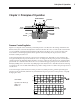
Figure 1
Pressure Controlling Valve
Figure 1 is a diagram of the electrically controlled pressure valve. Based on the setting of the IPAP and
EPAP controls, the control circuit adjusts the electrical current in the valve coil. The electric current in the
coil, in combination with the magnetic field from the magnet, produces a force on the valve disc. The
force that the coil and magnet generate must equal the force created by the air pressure in order to
maintain a stable pressure level.
As the patient breathes, flow into the valve increases and decreases. This tends to cause swings in the
force generated by the air pressure inside the valve. As changes from the preset pressure are sensed, the
electrical current automatically adjusts the disc to increase or decrease the amount of air vented from the
pressurized valve chamber. This allows the valve to maintain the appropriate pressure (whether IPAP or
EPAP) by adding flow to the circuit or by dumping it at the internal valve outlet. Because the monitoring
is continuous, the valve module immediately responds to changes in flow to deliver the preset pressure at
a stable level.
As shown in Figure 2, this method of control provides very stable pressures, permits rapid changes in
pressures to the preset IPAP/EPAP levels, and maintains the preset pressures in the presence of rapidly
changing flow rates.
Principles of Operation
MAGNET
COIL
VALVE DISC
PRESSURE
CHAMBER
AIR FROM
BiPAP UNIT
SS
NN
AIR TO
PATIENT
BiPAP EXHAUST
V
P
est
5 cm H O
2
1 second
60 L/min.
1 second
60 L/min.
0
Figure 2
SETTINGS:
Spontaneous Mode (S)
IPAP = 15
EPAP = 5