
User manual

15
User Manual
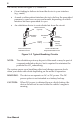
4.2.4 br e a T h i n g Ci r C u i T Co n n e C T i o n
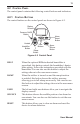
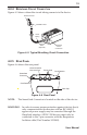
Figure 4–5 shows where the circuit tubing connects to the device.
Breathing
Circuit
Connection
Circuit
Tubing
Patient Interface
Bacteria
Filter
(Optional)
Exhalation Port
Figure 4–5 Typical Breathing Circuit Connection
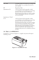
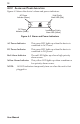
4.2.5 re a r pa n e l
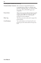
Figure 4–6 shows the rear panel.
Communications
Connector Port
Power Inlets
SmartCard
Connector
Filter Cap
Cord Retainer
Cord Retainer
Figure 4–6 Rear Panel
NOTE: The SmartCard Connector is located on the side of the device.
WARNING: In order to ensure proper protection against electric shock,
onlycommunicationsaccessorieswithanIEC60601-1
approved power supply may be connected through the
SleepLink interface. All IEC 950 devices must only be
connectedtothe7-pinconnectorwiththeRespironics
Isolation cable (Part Number 1012865).