
User manual

10
User Manual
Ch a p T e r 4: Co n T r o l s a n d
di s p l a y fe a T u r e s
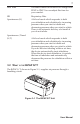
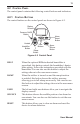
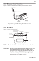
Figure 4–1 shows the location of the device’s alarm power indicators,
control panel, Pressure On/Off button, and breathing circuit connection.
Breathing Circuit
Connection
Control Panel
Pressure On/Off
Button
Alarm and Power Indicators
Figure 4–1 Front and Top
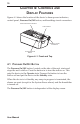
4.1 pr e s s u r e on/of f bu T T o n
The Pressure On/Off button, located on the side of the unit, starts and
stopstheunit’sairow.Pressthebuttonintoturntheairowon.This
puts the device in the Operate state. Depress the button to turn the
airowoffandputthedeviceintheStandby state.
WhenthedeviceisinStandby,anyrampinprogressisterminated,the
alarmsarereset(exceptfortheSystemErrorsalarm),andthehumidier
is turned off.
The Pressure On/Off button is independent of the display screen.