
User manual


User Manual
9
CHAPTER 4: DEVICE CONTROLS AND DISPLAY FEATURES
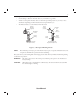
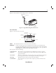
Figure 4–1 shows the location of the device’s alarm power indicators, control panel, Pressure On/Off
button, and the breathing circuit connection.
Breathing Circuit
Connection
Pressure On/Off Button
Control Panel
Alarm and Power
Indicators
Figure 4–1 Device Front and Top
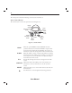
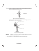
4.1 PRESSURE ON/OFF BUTTON
e device’s Pressure On/Off button, located on the side of the device, starts and stops the device’s
airfl ow.
• To turn the airfl ow on, press the button in, as shown in Figure 4–2. is puts the device in the
Operate state.
• To turn the airfl ow off , press the button again. is puts the device in the Standby state.
A
irflow
On
Airflow
Off
Figure 4–2 Pressure Button On/Off Positions
When the device is in Standby, any ramp in progress is terminated, the alarms are reset (except for the
System Errors alarm), and the humidifi er is turned off .
e button is independent of the display screen.