
User guide


Revision 1.2D Page 9 of 17
www.resourcedm.com
ML Switch User Guide
Warning
Please Note
The specifications of the product detailed on this
Set-Up Guide may change without notice. RDM
Ltd. shall not be liable for errors or for incidental
or consequential damages, directly and indirectly,
in connection with the furnishing, performance or
misuse of this product or document.
Ensure that all power is
switched off before
installing or maintaining
this product
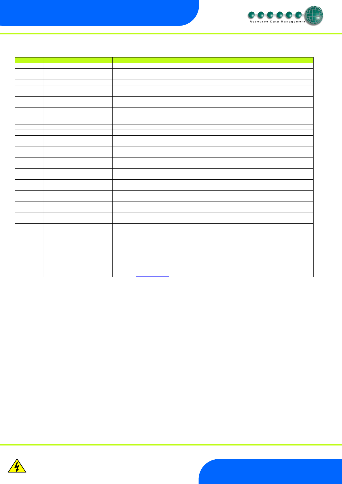
Parameters Description:
Number
Parameter
Description
P-01
Refrigerant
Select the gas type used within the refrigeration system.
P-02
Span
Total range of transducer*
P-03
Offset
Value below zero*
P-04
Glide
Glide characteristic (Offset to Evap Temperature)
P-05
Pressure Type
Select between Absolute or Gauge pressure
P-11
Evap 1 offset
Pressure difference between suction transducer and evaporator 1
P-12
Evap 2 offset
Pressure difference between suction transducer and evaporator 2
P-13
Evap 3 offset
Pressure difference between suction transducer and evaporator 3
P-14
Evap 4 offset
Pressure difference between suction transducer and evaporator 4
P-15
Evap 5 offset
Pressure difference between suction transducer and evaporator 5
P-16
Evap 6 offset
Pressure difference between suction transducer and evaporator 6
P-17
Evap 7 offset
Pressure difference between suction transducer and evaporator 7
P-18
Evap 8 offset
Pressure difference between suction transducer and evaporator 8
P-19
Evap 9 offset
Pressure difference between suction transducer and evaporator 9
P-20
Evap 10 offset
Pressure difference between suction transducer and evaporator 10
P-31
Transducer Fault Delay
Alarm generated, once transducer fault delay expires, if the transducer fails.
P-32
Alarm Delay
Delay before the HP alarm is generated.
P-33
HP Alarm
If the pressure exceeds this value then a High Pressure alarm is generated once the alarm
delay expires.
P-40
MOP
If the pressure exceeds this value the valves on controllers connected to the ML Switch will
closed or be reduced to a predetermined percentage. A MOP alarm is also created. (See MOP)
P-41
MOP Diff
When the pressure reduces below this value valves on controllers connected to the Switch will
recover to their normal operational
P-42
Recovery Count
When the Switch comes out of MOP, the valves will come on at 1 minute intervals and turn
“this” number of valves on per minute.
P-43
MOP Delay
Delay after the MOP value has been exceeded before the MOP actions and alarm occurs.
P-50
Humidity Low
Sets humidity low level.
P-51
Humidity High
Sets humidity high level.
P-52
Trim Low
Sets trim low level.
P-53
Trim High
Sets trim high level.
P-54
Trim Off Level
When the timer is in the off period the trims will be pulsed at this value. Note if the humidity
sensor fails the trim relays will be pulsed at this level.
P-55
Trim Mode
Off – Pulses the controller trim relays at the Trim Off Level.
On - trim control feature will continuously pulse the controller trim relays dependant
on the measured humidity.
Re mote – Uses Data Manager GP Timer channel to determine when to control. See
GP Timer Setup
* Span and Offset allows for the full range of the transducer to be used by the ML Switch.
Span is the full range of the transducer
Offset is the value below zero.
E.g. Danfoss AKS 33 with range: -1 bar to 12 bar
Span would be 190 (13 bar)
Offset would be -15 (-1 bar)