PR0109 PR0109-PHI ML Switch User Guide Resource Data Management Ltd 80 Johnstone Avenue, Hillington Industrial Estate, Glasgow, Scotland G52 4NZ UK +44(0)141 810 2828 Switchboard support@resourcedm.com Technical Support sales@resourcedm.com Sales Enquiries www.resourcedm.
ML Switch User Guide Table of Contents: ML SWITCH ........................................................................................................................................................ 3 Description ......................................................................................................................................................... 3 Front View ..............................................................................................................................
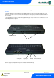
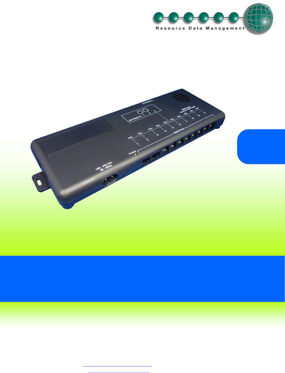
ML Switch User Guide ML Switch From Resource Data Management Description The ML Switch (PR0109) is a device that allows up to 10 RDM ML controllers to be connected to an IP network, without the need for individual IP ML modules. There are 10 RS232 connections for linking to 10 ML controllers. There are 3 standard Ethernet Switch (10/100baseT) connections for other network devices. The Ethernet ports are self configuring for uplinks and standard 10/100 Base T device connections.
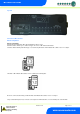
ML Switch User Guide Top View Connection to ML Controllers: Network Configuration Network Compatibility New ML Switch and IP Modules will be labeled identifying software version. New ML Controllers will not log on to network using pre 1.2 versions of ML Switch and IP Modules. Controllers with the following label will only log on to network using ML Switch or ML IP Module with software version 1.2 or higher. ML Switch or ML IP Module with software version 1.2 will have the following label.
ML Switch User Guide RS232 Lead Lengths RS232 patch lead maximum length must not exceed 15 metres. (Ports 1 - 10) The 3-character address that will be seen on the system front end is determined by the position of the two Network ID rotary switches and the port the controller has been connected to, unless the connected controller has its own network ID rotary switches, in which case the controller ID will override the switch settings.
ML Switch User Guide PR0109-PHI user guide The PR0109-PHI hardware version of the ML Switch allows for EEV control on an island by island basis. It also allows for the use of the energy feature trim control which pulses the trim relay of a ML case controller based on the actual shop floor humidity therefore minimising energy usage. Island EEV Control Application Product PR0109-PHI is intended for EEV control on an Island by island basis.
ML Switch User Guide Click on “Configure” to set the type: - Then click “Type” Use the drop-down selection to select the type required and then click “Set Type” Parameters can be configured using the connection as illustrated above or through the ML Display, if fitted, or via the normal Data Manager change parameter routes. Warning Revision 1.2D Ensure that all power is switched off before installing or maintaining this product Page 7 of 17 www.resourcedm.
ML Switch User Guide Parameters Number P-01 Parameter Refrigerant P-02 P-03 P-04 P-05 P-11 P-12 P-13 P-14 P-15 P-16 P-17 P-18 P-19 P-20 P-31 P-32 P-33 P-40 P-41 P-42 P-43 P-50 P-51 P-52 P-53 P-54 P-55 Span Offset Glide Pressure Type Evap 1 offset Evap 2 offset Evap 3 offset Evap 4 offset Evap 5 offset Evap 6 offset Evap 7 offset Evap 8 offset Evap 9 offset Evap 10 offset Transducer Fault Delay Alarm Delay HP Alarm MOP MOP Diff Recovery Count MOP Delay Humidity Low Humidity High Trim Low Trim High Trim O
ML Switch User Guide Parameters Description: Number P-01 P-02 P-03 P-04 P-05 P-11 P-12 P-13 P-14 P-15 P-16 P-17 P-18 P-19 P-20 P-31 P-32 P-33 Parameter Refrigerant Span Offset Glide Pressure Type Evap 1 offset Evap 2 offset Evap 3 offset Evap 4 offset Evap 5 offset Evap 6 offset Evap 7 offset Evap 8 offset Evap 9 offset Evap 10 offset Transducer Fault Delay Alarm Delay HP Alarm P-40 MOP P-41 MOP Diff P-42 Recovery Count P-43 P-50 P-51 P-52 P-53 P-54 MOP Delay Humidity Low Humidity High Trim Low Tr
ML Switch User Guide Input/Output table Number I-01 I-02 I-03 I-04 I-05 I-06 I-07 I-08 I-09 I-10 I-11 I-12 I-13 O-01 O-02 O-03 O-04 O-05 O-06 O-07 O-08 O-09 O-10 O-11 O-21 O-31 O-32 IO Evap Press Evap 1 Press Evap 2 Press Evap 3 Press Evap 4 Press Evap 5 Press Evap 6 Press Evap 7 Press Evap 8 Press Evap 9 Press Evap 10 Press Humidity Sensor Temp Evap Temp Evap 1 Temp Evap 2 Temp Evap 3 Temp Evap 4 Temp Evap 5 Temp Evap 6 Temp Evap 7 Temp Evap 8 Temp Evap 9 Temp Evap 10 Temp MOP Trim Level Remote Trim Wa
ML Switch User Guide EEV Control Operation Ensure the transducer is correctly connected and the jumper is in the Pressure position. Once the Switch has been correctly setup, it will pass values to each of the controllers connected to ports 1 through 10. In an EEV application the evaporator in temperature probe reading for a case controller can be obtained from the ML Switch on which the controller is connected.
ML Switch User Guide Humidity Control Operation To utilise this feature a Humidity/Temperature Display is required (PR0445). Connect the Humidity/temperature display to the display port on the ML Switch. The control algorithm will use the humidity reading from the display in calculating the percentage at which the trim relays are to be pulsed.
ML Switch User Guide Front Panel Features (PR0445) 4 Character LCD Down Button Enter Button # Button Up Button Display: The display fits a standard UK single socket pattress. Enter Button: Button used to enter/confirm values after a change. Up Button: When in the software menu, the up button is used to scroll up through the menu items.
ML Switch User Guide Setup Mode Setup through front buttons To enter the software menu for setup mode, hold the Enter and Down buttons together for approximately 3 seconds until the message “Ent” appears on the display. Release both buttons and now press the Enter button again to enter the software menu. IO is the first item to be displayed. Scroll up or down to go through the menu items which are highlighted below.
ML Switch User Guide Set/View Parameters (This can be achieved at the network front end) a. From the function menu scroll to select PArA b. Pressing Enter while PArA is displayed will enter the parameter menu. The first parameter option will be displayed as P01. Pressing the Up or Down button will present the other parameter options P-02, P-03 etc. See the parameter tables to find what parameter number corresponds to which actual parameter.
ML Switch User Guide IP-r (IP Address issued by the DHCP server) To configure the ML Switch for IP-r, set the two rotary switches to give the ML Switch unique identifier. The ML Switch should then be connected to the network. 2. nEt. From the function menu you can now select nEt Press enter and the display will show “IP-r”, press enter You can now view only the address given by the DHCP server To ease setup, a single network mask length value is used.
ML Switch User Guide Specification Power requirements: Supply Voltage Range: Supply Frequency: Typical supply current: Maximum supply current Operating temperature range: Operating Humidity: Storage temperature range: Environmental: Size: Weight: Safety: EMC: Ventilation: Class 2 Insulation: 100 - 240 Vac ±10% (Mains version) 50 - 60 Hz (Mains version) <500 mAmps 650mA +50C to +500C 80% maximum -200C to +650C Indoor use at altitudes up to 2000m, Pollution Degree 1, Installation Category II.