Mercury PR0710-MOB PR0720-MOB Intuitive PR0750-MOB PR0760-MOB Mercury 2 & Intuitive Mercury Mobile Controller Installation & User Guide For Products: - PR0710, PR0711, PR0720, PR0721 Resource Data Management UK OFFICE Resource Data Management Ltd 80 Johnstone Avenue, Hillington Industrial Estate, Glasgow, Scotland, G52 4NZ, UK +44(0)141 810 2828 sales@resourcedm.
Mercury 2 & Intuitive Mobile Controller User Guide Table of Contents: ............................................................................................................................................................................. 1 THE MERCURY & INTUITIVE RANGE .............................................................................................................. 4 Variants ................................................................................................................
Mercury 2 & Intuitive Mobile Controller User Guide Fixing .............................................................................................................................................................. 19 Dimensions ...................................................................................................................................................... 19 Dimensions ...................................................................................................................
Mercury 2 & Intuitive Mobile Controller User Guide The Mercury & Intuitive Range From Resource Data Management For Version Mob 1.0 The Mercury Mk2 Mobile controller is intended for use in refrigeration display cabinets with one or two integral compressors with each compressor having a temperature probe fitted to enable the compressor to be stopped if a set (discharge) temperature is exceeded.
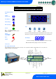
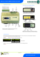
Mercury 2 & Intuitive Mobile Controller User Guide Description Intuitive Internal IP Network Card Interface Kit Intuitive Internal RS485 Network Card Interface Kit Intuitive Internal Wireless Mesh Network Card Interface Kit Part Number PR0770 PR0771 PR0772 Front Display Features LED’s: Cooling (Relay 1 or 4) Fans (Relay 2) Lights (Relay 3) Defrost (Relay 5) Keys On-Line Off No network attached Flashing Attempting to Log on to network Steady On-line Enter Up Down Defrost Note: Function keys illumi
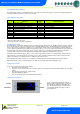
Mercury 2 & Intuitive Mobile Controller User Guide Intuitive Mercury Controller Common Compressor B Out Not Used Common Defrost Out Not Used Logging Probe Common Defrost Probe Common Comp B Disch. Common Comp A Disch. Common Air Off Probe Common Air On Probe Common Intuitive Mercury Network Expansion Options RS232 Network Card (Default) The Intuitive Mercury is supplied with an RS232 Network Card fitted as standard.
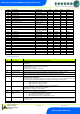
Mercury 2 & Intuitive Mobile Controller User Guide Input and Output Allocation Tables The following tables indicate; on a controller type basis, the functions of the inputs and outputs. Also shown are the digital inputs that are derived by switching in a fixed value resistor across the input.
Mercury 2 & Intuitive Mobile Controller User Guide Setup Function Menu Display IO PArA Unit diSP tyPE rtc Option View Inputs / Outputs and States Set/View Parameters Probe type and Celsius/Fahrenheit option Display whole units or decimal Set/View Controller Type Set/view Clock (rtc = Real Time Clock) Explained in Paragraph Input / output table Display Explained in Paragraph Network Configuration Option nEt Set/view network configuration Set view parameters SoFt View software version Set View Uni
Mercury 2 & Intuitive Mobile Controller User Guide Display From the function menu scroll to and select diSP. Press enter and one of the following values will be shown: 0. Controller display will show the whole number and tenths value of a temperature reading. (Default) 1. Controller display will show temperatures as a whole number. Parameter Tables Number Parameter Range Step o C ( oF ) -42 to 30 (-43.6 to 86) 0.1 0 to 10 (0 to 18) 0.
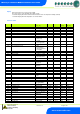
Mercury 2 & Intuitive Mobile Controller User Guide P-46 P-47 P-48 P-89 P-86 P-49 P-88 P-50 P-91 Def Max Time Drain Down Recovery Time Pump Down Time Fan Delay mode Fan Delay Time Fan Delay Temp Fans In Defrost Defrost Type (Integral) P-94 P-95 P-96 P-60 Defrost Hold Defrost Skip Defrost Skip Time Lights Mode P-61 P-62 P-63 P-64 P-65 P-66 P-67 P-68 P-69 P-70 P-71 P-72 P-73 P-74 dFLt Sun Lights On Sun Lights Off Mon Lights On Mon Lights Off Tue Lights On Tue Lights Off Wed Lights On Wed Lights Off Thu L
Mercury 2 & Intuitive Mobile Controller User Guide P-16 Relay 3 mode P-29 Probe 1 or Probe 3 Resistor Service Interval Time (Run Hours) P-18 P-19 Switch Resistors P-98 Lights Case Off P-99 Load Shedding P-30 Do Discharge Stop Compressor A Do Discharge Stop Compressor B Discharge Stop Value P-31 P-32 P-33 P-35 Discharge Stop Differential Maximum Compressor Run Time Comp Stop Both P-20 P-21 P-22 P-23 Alarm Delay UT Alarm OT Alarm Log Probe Type P-24 Slug Log Probe P-25 P-26 P-27 P-28 P-40
Mercury 2 & Intuitive Mobile Controller User Guide P-46 P-47 P-48 Def Max Time Drain Down Recovery Time P-89 P-86 Pump Down Time Fan Delay mode P-49 P-88 P-50 Fan Delay Fan Delay Temp Fans In Defrost P-91 Defrost Type P-94 Defrost Hold P-95 Defrost Skip P-96 Defrost Skip Time P-60 Lights Mode P-61 P-62 P-63 P-64 P-65 P-66 P-67 P-68 P-69 P-70 P-71 P-72 P-73 P-74 dFLt Sun Lights On Sun Lights Off Mon Lights On Mon Lights Off Tue Lights On Tue Lights Off Wed Lights On Wed Lights Off Thu Light
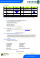
Mercury 2 & Intuitive Mobile Controller User Guide Relay and screen states during defrost State: Screen: Def LED: RLY 1 Comp A (Defrost set to gas) RLY 1 Comp A (Defrost set to electric) RLY 1 Comp A (Defrost set to elec/cln) RLY 4 Comp B RLY 5 Defrost Relay RLY 3 Lights relay (Timer channel On) RLY 2 Fans (On in DF) RLY 2 Fans (Off in DF) Pump Down DEF On Off Off Off Off Off On On Off Defrost Min DEF On On Off Off Off Off/Cycles* On On Off Defrost Max DEF On On Off Off Off On On On Off Drain Down DEF
Mercury 2 & Intuitive Mobile Controller User Guide Wireless Mesh Communication Module RDM Wireless Mesh System, please refer to the RDM Wireless Mesh Communication Module user guide, which can be obtained from the RDM website, for information regarding connecting a controller to a Wireless Mesh network. The value shown in 485A is of the form 05-6. This means the controller would try to log onto a Genus compatible or RDM Wireless Mesh network using the name ‘RC05-6’.
Mercury 2 & Intuitive Mobile Controller User Guide IP-r To configure the communication module for IP-r, set the three rotary switches to give each controller a unique identifier. The module should then be connected to the controller and the network. In the case of an Intuitive Mercury controller where the network card is already fitted, the three rotary switches must be set when the controller is powered off, the controller should then be powered on to connect to the network. 2. nEt.
Mercury 2 & Intuitive Mobile Controller User Guide O-12 O-13 Last Def. Ctrl Temp. Last Def. Type O-16 O-18 O-30 S-01 Alarm Relay Run Time Set Point Offset Control State -42 to 60 (-43.6 to 140) 0 (None), 1 (Internal), 2 (External), 3 (Network), 4 (Display), 5 (Timed) 6 (Forced), 7 (Skipped) 0 (Unused), 1 (OK), 2 (Alarm) 0 – 128 K Hours -49 to 60 (-56.
Mercury 2 & Intuitive Mobile Controller User Guide Fans Only “FAnS” Selecting the Fans Only option will put the controller into the Fans Only state if the current state is not Fans Only. If the current state is Fans Only then the controller will change to the Normal state. Selecting this option will exit the setup menu automatically.
Mercury 2 & Intuitive Mobile Controller User Guide Specification Mercury Mk2 Controller PR0710-MOB & PR0720-MOB Intuitive Mercury controller PR0750-MOB & PR0760-MOB 100 - 240 Vac ±10% 50 - 60 Hz 5.2 Amps (when relay 5 is fully loaded) <1 Amp 100 - 240 Vac ±10% 50 - 60 Hz 2 Amps <1 Amp +50C to +500C -200C to +650C Indoor use at altitudes up to 2000m, pollution degree 1, installation category II. Voltage fluctuations not to exceed ±10% of nominal voltage.
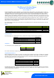
Mercury 2 & Intuitive Mobile Controller User Guide Inputs Input resistance: Input type 3.01K Ohms (for PTC or NTC type probes) Selectable. See: Units Comms: RS232 with flow control Switched Resistor Example Wiring Example of resistor fitted on a probe input. Connect to remote switch or relay Probe Ground Probe Signal Installation Panel Cut-out and Clearances Mercury Mk2 (Flush mount controller) Fixing The controller is fixed by sliding the 2 plastic retaining clips up to rear of the panel.
Mercury 2 & Intuitive Mobile Controller User Guide Dimensions Intuitive Mercury controller Intuitive Mercury Mounting Instructions Three clips fix the Intuitive Mercury securely to DIN rail. Pull each clip until it “clicks” to remove the controller. Each clip has a mounting hole to provide an alternative fixing mechanism to DIN mounting. Cleaning Do not wet the controller when cleaning. Clean the front by wiping with slightly damped lint free cloth.
Mercury 2 & Intuitive Mobile Controller User Guide Revision History Revision Date Changes 1.0 1.1 1.2 23/01/2014 29/01/2014 17/02/2014 First Issue Maximum Compressor Run Time description added. P-35 “Comp Stop Both” parameter added. Warning Ensure that all power is switched off before installing or maintaining this product Revision 1.2 Page 21 of 21 www.resourcedm.