
Installation guide

Warning
Please Note
The specifications of the product detailed on this
Set-Up Guide may change without notice. RDM
Ltd. shall not be liable for errors or for incidental
or consequential damages, directly and indirectly,
in connection with the furnishing, performance or
misuse of this product or document.
Ensure that all power is
switched off before
installing or maintaining
this product
Revision 2.7 Page 81 of 83
Mercury Plant Controller Installation Guide
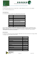
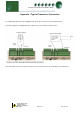
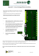
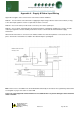
Appendix 3 – Supply & Status Input Wiring
Appendix three applies to earlier versions of the Plant controller hardware. Connection of the supply voltage and
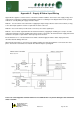
status inputs is important so that the internal bridge rectifier is not damaged. The diagram below shows possible
methods of correctly wiring the supply and status inputs.
Method 1. Uses the 24Vac of the transformer supplying the input voltage; which is returned via a switch (or relay)
to the status input signal line. No 0V is required at the status connector.
Method 2. Uses a 0V return (from the status connector) to the status signal input.
Method 3. Uses a 24Vac signal derived from another transformer (supplying an auxiliary piece of kit) to feed the
status input signal line. Note the auxiliary transformer must be referenced to the Plant Controller supply transformer
and that no 0v signal is required at the status input ground connection.
Ensure that there is no connection between the Plant controller Supply 0V and the Status input ground 0V;
otherwise internal damage will occur.
All transformers that have a connection to the Plant Controller must have their primaries connected to the same
phase. Transformer should have fuse fitted in line with 24V input as per diagram.
The use of centre tapped to earth transformers is not allowed. This is to prevent damage to the transformer
and/or controller.
Without Status LED