
Installation guide

Warning
Please Note
The specifications of the product detailed on this
Set-Up Guide may change without notice. RDM
Ltd. shall not be liable for errors or for incidental
or consequential damages, directly and indirectly,
in connection with the furnishing, performance or
misuse of this product or document.
Ensure that all power is
switched off before
installing or maintaining
this product
Revision 2.7 Page 80 of 83
Mercury Plant Controller Installation Guide
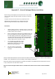
Instructions
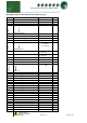
1. Align the Plant controller in a vertical position as shown and
remove the plastic top cover. The four screws are accessed
from the bottom of the controller.
2. Before removing the modem from its' packaging, make sure
that you are static free. Insert the modem into it’s' socket in
the main printed circuit board, ensuring that the device is
correctly orientated. Care must be taken when pushing the
modem into its socket that all pins are correctly lined up
and go neatly into their respective sockets.
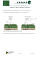
Appendix 2 – Internal Analogue Modem Installation
With the modem fitted it allows for remote access to the Plant controller only. There are no “dial out” alarm features
available. This setup will allow for remote viewing of and changing of parameters.
Refer to the “Mercury Plant Controller PC Connection User Guide” on the RDM web site for instructions on how to
set up a remote PC connection via the modem.
Note: the internal analogue modem feature is available with earlier versions of Plant controller hardware
only.
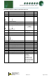
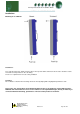
3. The orientation when fitting the modem
is as follows: Identify the corner of the
PCB that has only two pins. The 2 pins
fit into the bottom-left position.
4. Once the modem is satisfactorily
positioned, re-assemble the Plant
controller.
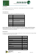
4
NETWORK
ADDRESS
U
S
B
H
O
S
T
1
&
2
U
S
B
D
E
V
I
C
E
D
I
S
P
L
A
Y
5
V
H
G
L
G
C
A
N
B
U
S
M
O
D
E
M
E
T
H
E
R
N
E
T
1
0
/
1
0
0
B
a
s
e
T
1
RELAY RATINGS:
5A/25 0 Vac/AC1
1
S
T
A
T
U
S
I
N
P
U
T
S
G
R
O
U
N
D
S
2
3
4
5
6
7
8
9
1
0
1
1
1
2
-
2
0
m
A
O
/
P
’
s
1
2
V
V
V
1
2
3
4
-
2
0
m
A
I
/
P
’
s
1
2
3
4
5
6
7
8
A
N
A
L
O
G
U
E
I
N
P
U
T
S
2
4
V
0
V
E
S
U
P
P
L
Y
I
N
P
U
T
2
4
V
A
C
o
r
D
C
R
L
Y
1
R
L
Y
2
R
L
Y
3
R
L
Y
4
R
L
Y
5
R
L
Y
6
R
L
Y
7
R
L
Y
8
R
L
Y
9
R
L
Y
1
0
R
L
Y
1
1
R
L
Y
1
2
G
R
O
U
N
D
S
Modem Device
Before working on this equipment, ensure that the device is fully isolated
from any supply voltage, including connections to all relays and other I/O
connectors.
Installation of this part must be carried out by competent personnel.
RDM will not be held responsible for any damage incurred to the
equipment through mishandling or faulty installation of this part.