
Installation guide

Warning
Please Note
The specifications of the product detailed on this
Set-Up Guide may change without notice. RDM
Ltd. shall not be liable for errors or for incidental
or consequential damages, directly and indirectly,
in connection with the furnishing, performance or
misuse of this product or document.
Ensure that all power is
switched off before
installing or maintaining
this product
Revision 2.7 Page 77 of 83
Mercury Plant Controller Installation Guide
Specification
Power requirements:
Supply Voltage Range: 24 Vac ±10% or 24 Vdc ±10%
Supply Frequency: 50 – 60 Hz ±10%
Maximum supply current: <1 Amp
Typical supply current: <1.0 Amp
Class 2 Insulation: No protective Earth is required. A functional earth can be connected if the
equipment is located in an electrically noisy environment.
Note : The use of centre tapped to earth transformers is not allowed.
This is to prevent damage to the transformer and/or controller.
The host equipment must provide adequate protection against contact to hazardous live parts.
RDM advise the use of a suitable external over-current protection device.
Warranty may be invalidated due to excess current being unlimited if there are no fuses/circuit breakers installed
General
Operating temperature range: +5
0
C to +50
0
C
Operating Humidity: 80% maximum
Storage temperature range: -20
0
C to +65
0
C
Environmental: Indoor use at altitudes up to 2000m, Pollution Degree 1,
Installation Category II.
Voltage fluctuations not to exceed ±10% of nominal voltage
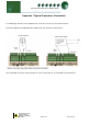
Size: 270mm (L) x 115mm (W) x 50mm (H)
Weight: 700 Grams
Safety: EN61010
EMC: EN61326; 1997 + Amdt. A1; 1998
Ventilation: There is no requirement for forced cooling ventilation
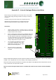
Inputs
Probe Input type See Set/change Units for probe types
Digital Input type The preferred option is a 0 volt return through a volt free relay or 24 Vac
referenced to the supply voltage. If a 24Vac signal is being sourced from the Plant
controller power supply then do not ground the Digital Input common rail, this is
grounded internally.
Comms: Ethernet
4-20mA 4-20mA current loop, use the 12 Vdc output to feed the device.
Analogue Outputs 0 to 5/10 Volts dc or 0/4-20mA, Selected in the Front Panel Menu.
A 50mA fuse is recommended for each Analogue output.
The 4-20mA output will not operate correctly if the target device input impedance
is > 75Ω
The 0-10V output will not operate correctly if the target device input impedance is
< 10KΩ
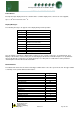
Relay Ratings
All Relays 5A/250 Vac/AC1 (Resistive load)
5A/30 Vdc (Resistive)
2A/250 Vac cosφ=0.3 on N/O contact (Inductive Load)