
Installation guide

Warning
Please Note
The specifications of the product detailed on this
Set-Up Guide may change without notice. RDM
Ltd. shall not be liable for errors or for incidental
or consequential damages, directly and indirectly,
in connection with the furnishing, performance or
misuse of this product or document.
Ensure that all power is
switched off before
installing or maintaining
this product
Revision 2.7 Page 76 of 83
Mercury Plant Controller Installation Guide
Probe Offsets
Each probe input, displayed as C-01 to C-08 from the controller display menu, can have an offset applied;
Up to ± 20
O
C in increments of 0.1
O
C.
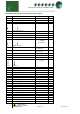
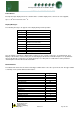
Display Messages
The following messages can appear on the display during normal operation.
Display
System status
HP
High Pressure alarm
LP
Low Pressure alarm
Ft TrAn
Pressure Transducer Fault
Ft
Fault
Sd
Low Pressure Shut-down
CP
Compressor Fault
Compressor Run Fault
Cd
Condenser Fan Fault
gn
General Fault
Stby
Controller in Standby
Conf
Configuration / Set up error
triP
Discharge Pressure Trip alarm
Note 10: If Only 1 Transducer is fitted and the controller is set to a single section type, for example Pack, then
Display 1 will show the current suction pressure but Display 2 will show Ft. Transducer input 2 is on by default to
allow for the fitment of a transducer for monitoring purposes. If this probe is not fitted then set the parameter
“Trans2 Span” to 0. This will clear the fault alarm.
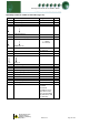
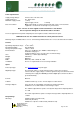
Network Alarms
The table below shows the text and associated type number that is sent to the system “front end”. The type number
is normally used to provide different alarm actions.
Alarm text
Type #
High Pressure Alarms
8
Low Pressure Alarms
9
Low Pressure Shutdown
10
Transducer Faults
6
General Faults
20
Compressor faults
3
Condenser Faults
3
Configuration fault
20
Controller in standby
20
INV Bypass
3
Liquid Level Fault
6
Liquid Level High
4
Liquid Level Low
5
Discharge Trip
20
Float Probe Fault
6
Drop Leg Probe Fault
6