
Installation guide


Warning
Please Note
The specifications of the product detailed on this
Set-Up Guide may change without notice. RDM
Ltd. shall not be liable for errors or for incidental
or consequential damages, directly and indirectly,
in connection with the furnishing, performance or
misuse of this product or document.
Ensure that all power is
switched off before
installing or maintaining
this product
Revision 2.7 Page 61 of 83
Mercury Plant Controller Installation Guide
Viewing
Inputs and Outputs
Apart from setting up the controller, you can also view the status of the inputs and outputs.
1. From the function menu, select “IO”, press enter
2. You can now scroll through the IO tables as set out below. The tables you view will depend on the
controller type configuration.
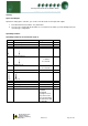
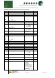
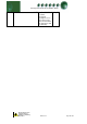
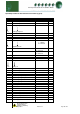
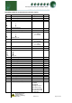
Input/Output Tables
Input/Output table for Pack Controller (Type 1)
Number
IO
Range
Units
I-01
Pressure Input 1
-3.4 - 180
Bar
I-02
Pressure Input 2
-3.4 - 180
Bar
I-03
Pressure Input 3
-3.4 - 180
Bar
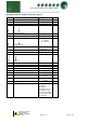
I-10
I-17
Analogue Input 1
Analogue Input 8
-60 to +128
O
C
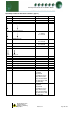
I-30
I-41
Digital Input 1
Digital Input 12
0 = OK
1 = Alarm
2 = Unused
I-50
Section 1 Run
0 = Off, 1 = On
2 = Unused
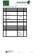
I-54
Liquid Level
0 – 100
%
O-01
O-12
Relay 1
Relay 12
0 = Off, 1 = On
O-31
Variable Output 1
0 – 100
%
O-41
Optimisation Level
-3.4 - 180
Bar
O-70
Sect 1 Bypass
0 = Off, 1 = On
O-72
Section 1 Gas Dump
0 = Off, 1 = On
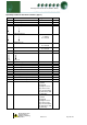
S-01
Section 1 Control States
(0) Stabilise
(1) Initial
(2) Normal
(3) High Pressure
(4) Low Pressure
(5) Low Shut-down
(6) Transducer Fail
(7) Standby