
Installation guide

Warning
Please Note
The specifications of the product detailed on this
Set-Up Guide may change without notice. RDM
Ltd. shall not be liable for errors or for incidental
or consequential damages, directly and indirectly,
in connection with the furnishing, performance or
misuse of this product or document.
Ensure that all power is
switched off before
installing or maintaining
this product
Revision 2.7 Page 57 of 83
Mercury Plant Controller Installation Guide
Relay Outputs – Configuration
Compressor(s)/Loader(s)/Fan(s) relays are assigned using the Stage parameters for a given section.
Additional relay outputs for a section will be assigned in the following order once the Stage parameters have been
configured. The following will be assigned to the first available relay(s): -
Condenser Split
Heat Reclaim
INV Bypass
Gas Dump
The first available relay after Section 1 and 2 are configured will become the Alarm Relay
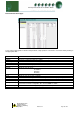
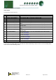
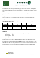
Section Stages
Stage
Description
None
Use this option to end the number of stages in the controller
See note 7
Unused
Use this option to skip a relay output within a stage
Comp
Use this option to assign a relay output to a compressor
See note 5
Loader
Use this option to assign a relay output to a compressor loader
See note 9
Fan
Use this option to assign a relay to a fan
Inverter
Use this option to assign a relay to an Inverter
Trim
Use this option to set a relay to a trim compressor
See note 6
Comp Run
Use this option to set a relay as a separate compressor used only
when other compressors are running
See note 8
Note 5: In a pack configuration, at least 1 output must be assigned to a compressor. Loader outputs will not
energise without a compressor being on. When assigning stages a Loader should follow the Compressor on which
it is mounted.
Note 6. This option can be used to delay the onset of the inverter output, all outputs selected as “Trim” will come on
before the Inverter output energises. Once all the trim stages are on the inverter enable relay would be energised
and the inverter analogue output would begin to ramp up. The trim stages would remain on until all other stages
and the inverter are turned off.
Note 8: This option is used to bring on a separate compressor. This output is active when any of the other defined
compressors (Comp stages) are running. This output is off when the last compressor in its section is turned off.
Note if only the inverter output is configured and no other Comp stages then the Comp Run is active when the
inverter output is active.
Note 9 : Relays can be configured as Loaders, selected after a Compressor stage or a Compressor running on an
Inverter
Alarm Relay
Note 7. The alarm relay is assigned automatically to the first free relay that has been assigned “None” in the stage
programming. At first power on this is likely to be relay 1, until programming of the output stage is complete. The
relay is energised with no alarm and de-energised when in alarm.
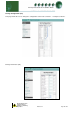
Stage Sizes
Stage sizes will determine the order in which compressors or loaders are switched on and off. This is a relative
number between 0 and 60, reflecting the size of the compressor (usually horse power)
The default stage size is 0; stage sizes must be entered for correct operation.