
Installation guide

Warning
Please Note
The specifications of the product detailed on this
Set-Up Guide may change without notice. RDM
Ltd. shall not be liable for errors or for incidental
or consequential damages, directly and indirectly,
in connection with the furnishing, performance or
misuse of this product or document.
Ensure that all power is
switched off before
installing or maintaining
this product
Revision 2.7 Page 51 of 83
Mercury Plant Controller Installation Guide
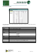
Example 2 (Type 1 Fuzzy)
Pack set up: 2 compressors with 2 Loaders each
Sect 1 stage 1 = Comp. Sect 1 stage 2 = Loader. Sect 1 stage 3 = Loader.
Sect 1 stage 4 = Comp. Sect 1 stage 5 = Loader. Sect 1 stage 6 = Loader.
Parameter P495 = 1 (On)
Switching On sequence: Pressure above set point + diff
First compressor comes on. First compressor loader 1 comes on. First compressor loader 2 comes on.
Second compressor comes on. Second compressor loader 1 comes on. Second compressor loader 2 comes on.
Switching Off sequence: Pressure below set point – diff
One compressor loader 2 goes off. Compressor loader 1 goes off.
Next compressor loader 2 goes off. Compressor loader 1 goes off.
One compressor body goes off. Next compressor body goes off.
This configuration switches off all loaders before switching off any compressor, thus leaving both compressors
running unloaded before switching one completely off.
NOTE: If using an Inverter with loaders
The Inverter and its loader/s will always be the last to go off.
Equal Run Times
With parameters P496/498 Set to 1 (On) the controller will bring on the compressors in a way that the running
times are as near equal as possible.
If the pressure is above set point, the next compressor that comes on will be the compressor that has been running
for the least amount of time.
If the pressure is below set point the next compressor to go off will be the one that has been running the longest.
This configuration, over time, will make all the compressor run hours as equal as possible.
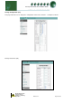
Inverter Bypass
Inverter Bypass Parameter (442/443) is used to set however many retries are required if the Inverter run signal is
not returned in the allocated time after the inverter enable has been turned on.
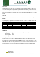
P442/443 set for 1 to 5 is the number of times enable comes on including initial inverter enable turned on.
0 = Feature disabled.
1 = Inverter enable will come on once with no retries
2 = Initial turn on and 1 retry
3 = Initial turn on and 2 retries
4 = Initial turn on and 3 retries
5 = Initial turn on and 4 retries
Firstly assign the desired inverter run input using the Status Fault inputs. This input can be set as either normally
closed (INV N/C) or normally open (INV N/O). When the inverter enable relay is called for by the control strategy
then the inverter run signal has to be returned to the appropriate input within 2 seconds.
If the run signal is received then the control strategy will continue as normally and the variable output will begin to
ramp up.
If the signal is not returned within the allotted time then the following will occur.
P442/443 set for 1 The inverter enable will stay off and bypass relay will come on.
P442/443 set for 2 to 5 The inverter enable relay will be turned off for a further 15 seconds.
This process will occur a further 1 to 4 retries depending on (P442/443) if the inverter run signal is not received in
any test instance. After the retries the inverter will be taken out of the control logic, until the fault is cleared using
the reset process, and the pack will operate as a standard digital pack without the use of the inverter output. At this
point the Bypass relay will become like another staged relay and will cycle on and off when called for.