
Installation guide

Warning
Please Note
The specifications of the product detailed on this
Set-Up Guide may change without notice. RDM
Ltd. shall not be liable for errors or for incidental
or consequential damages, directly and indirectly,
in connection with the furnishing, performance or
misuse of this product or document.
Ensure that all power is
switched off before
installing or maintaining
this product
Revision 2.7 Page 49 of 83
Mercury Plant Controller Installation Guide
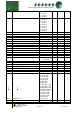
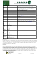
1 = On (Uses Ext Set Point)
2 = On Rly(Uses Ext Set Point and allocates a Relay)
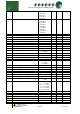
P475
Discharge trip
If Discharge Pressure exceeds this setting All compressors
go off immediately and all fans come on immediately. A
Discharge Trip Alarm is generated.
P476
Discharge Trip Diff
Diff below for parameter P-475 at which point control goes
back to normal and alarm clears.
P472
Run Proof
See section Run-Proof
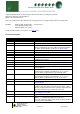
P-60
Status fault Delay
Time delay before status faults are activated
P-61
General Alarm Delay
Time delay before general faults are activated
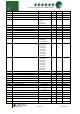
P480
Liquid Level
Enable for Liquid Level feature
See Note : Liquid Level
P481/482
Liquid Level Alarm
Settings at which High and Low Liquid Level alarms are
generated
P483
Liquid Level Alarm Delay
Delay applied before the Low or High liquid alarm is
generated.
P494
Dual Standby
Used to place two sections into Standby from one Standby
status input. (Note “Std 1 N/O or Std 1 N/C must be utilised
when using this feature) See Note Standby Mode
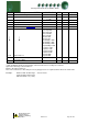
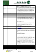
P-80
P-91
Status Fault 1
Status Fault 12
Used to select the type of input required
P100/140
Fuzzy
P111/151
Fuzzy
Stage 1
Stage 12
Select the output device for this stage
P120/160
Fuzzy
P131/171
Fuzzy
Stage 1 Size
Stage 12 Size
Sets the relative size for each compressor
Parameters
for Staged
type
Stage 1 Relay 1 to 12
Stage 12 Relay 1 to 12
Maps compressor relays to stages
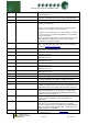
Liquid Level
Liquid Level Detector uses 4-20mA Input 3 on the Plant controller. Where 4mA will give a reading of 0% and 20mA
will give a reading of 100%. The Span and Offset parameters for Transducer input 3 do not require adjustment and
can be left at the default values. “Low Liquid Level Alarm” (P-482) and “High Liquid Level Alarm” (P-481) can be
generated. The alarm has a settable delay.
Run-Proof
This is a “global” parameter if set to on the Status fault inputs are used to prove that compressors are running.
Configure the status inputs, using either Compressor Normally Closed or Compressor Normally Open, that
correspond with each relay output. When the relay output is energised and the run proof signal isn’t returned within
the specified time period, then the compressor relay will go off and be taken out of the control strategy until the run
proof has been reset. The run-proof feature uses the status fault delay (P-60) and all run proof signals must be
returned within this delay period. Run proofs are used with compressor (Comp) stages only. This feature can be
used in both Fuzzy and Staged applications.