
Installation guide

Warning
Please Note
The specifications of the product detailed on this
Set-Up Guide may change without notice. RDM
Ltd. shall not be liable for errors or for incidental
or consequential damages, directly and indirectly,
in connection with the furnishing, performance or
misuse of this product or document.
Ensure that all power is
switched off before
installing or maintaining
this product
Revision 2.7 Page 46 of 83
Mercury Plant Controller Installation Guide
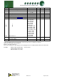
* Span and Offset allows for the full range of the transducer to be used by the controller.
Span is the full range of the transducer
Offset is the value below zero.
Note. The controller uses absolute pressure; if gauge pressure is required, add +1 Bar to the offset value.
Example: Danfoss AKS 33 with range: -1 bar to 12 bar
Span would be 190 (13 bar)
Offset would be -15 (-1 bar)
If only transducer input 1 in use please see Note 10 also.
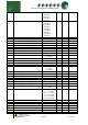
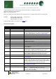
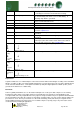
Parameter Description:
Number
Parameter
Description
P-01/03/05
Transducer 1/2/3 Span
Range of the transducers
P-02/04/06
Transducer 1/2/3 Offset
Transducer value below zero.
P-20/40
Target Pressure
Pressure target, control will try to maintain this pressure
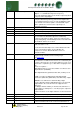
P473/474
External Target Pressure
Pressure target when Sect1 Run/Sect2 Run is off. Control
will try to maintain this pressure until Sect1 Run/Sect2 Run is
on. At this point P-20/40 used. Please see Status Inputs
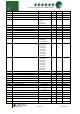
P-21/41
Target Pressure Above P-20
Set-point above the target, used to obtain a “dead-band”
P-22/42
Target Pressure Below P-20
Set-point below the target, used to obtain a “dead-band”
P-23/43
Number of Stages
Number of stages in the system
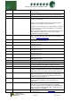
P-23/43Fzy
Starts per hour
Limits a compressor to this many starts per hour
P-24/44Fzy
Run smallest
See explanation under the parameter tables for this
parameter Run Smallest
P-24/44Stg
Stage-on Delay
Delay time between stages on (Staged types only)
P-25/45Stg
Stage-off Delay
Delay time between stages off (Staged types only)
P-26/46
Inverter
Enables the inverter analogue output and associated relay.
P442/443
Inverter Bypass
Enable for Inverter Bypass feature.
See INV Bypass
P444/445
Inverter Min
The minimum percentage the inverter will operate to when
Inverter Bypass parameter (P-442/443) is on e.g. if set to
25% the inverter output will never go below this value
P446/447
Inverter Max
The maximum percentage the inverter will operate to when
Inverter Bypass parameter (P-442/443) is on e.g. if set to
80% the inverter output will never go above this value
P490/491
Section 1/2 Gas Dump
Enables Gas Dump feature.
P492/493
Section 1/2 Gas Diff
Diff below the set point that the Gas Dump valve is opened.
See Gas Dump
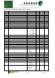
P470/471
Always run last
Keeps the last stage running except for a Low Shutdown
condition. If the last stage is an inverter, the inverter enable
will stay energised, but the inverter analogue output may well
decrease to 0% if pressure is below the set-point.
P495/497
Sect 1 / 2 Compressor Unload
Selects the order the compressor loaders are switched off
See: Compressor Loaders
P496/498
Sect 1 / 2 Equal
Equalises compressor run times. See: Equal run Times
P-27/47
Response On Speed
Allows the user to speed up/slow down the stage on speed
(Option: - 1 to 60 with 60 being fastest response)
Note: This parameter applies to the inverter output only when
using any of the Staged types.