
Installation guide


Warning
Please Note
The specifications of the product detailed on this
Set-Up Guide may change without notice. RDM
Ltd. shall not be liable for errors or for incidental
or consequential damages, directly and indirectly,
in connection with the furnishing, performance or
misuse of this product or document.
Ensure that all power is
switched off before
installing or maintaining
this product
Revision 2.7 Page 13 of 83
Mercury Plant Controller Installation Guide
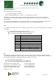
PArA. Set/view parameters
1. From the function menu scroll to PArA
2. Pressing Enter while PArA is displayed will enter the parameter menu.
The first parameter option will be displayed as P-01. Pressing the Up or Down button will present the other
parameter options P-02, P-03 etc. See the parameter list below to find what parameter number corresponds to
which actual parameter.
Pressing the Enter button will show the current value of the selected parameter. Press Up or Down to modify the
value and press Enter again to save the value. The parameter list number will be displayed again.
Two other options are present in the parameter menu – dFLt and ESC. Selecting ESC will exit the parameter set-
up mode. Selecting dFLt will reset all parameters back to the default values for the current controller type.
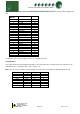
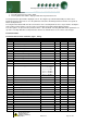
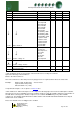
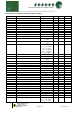
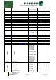
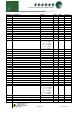
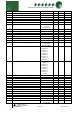
Parameter Tables:
Parameter table for Pack Controller (Type 1, Fuzzy)
Number
Parameter
Range
Step
Units
Default
P-01
Transducer 1 Span *
-3.4 - 180
0.1
Bar
13.8
P-02
Transducer 1 Offset
-3.4 - 180
0.1
Bar
0
P-03
Transducer 2 Span *
-3.4 - 180
0.1
Bar
13.8
P-04
Transducer 2 Offset
-3.4 - 180
0.1
Bar
0
P-05
Transducer 3 Span *
-3.4 - 180
0.1
Bar
13.8
P-06
Transducer 3 Offset
-3.4 - 180
0.1
Bar
0
P-20
Section 1 Target Pressure
-3.4 - 180
0.1
Bar
2.1
P473
Section 1 External Target Pressure
-3.4 - 180
0.1
Bar
3.1
P-21
Section 1 Target Pressure Above P-20
-3.4 - 180
0.1
Bar
0.5
P-22
Section 1 Target Pressure Below P-20
-3.4 - 180
0.1
Bar
0.5
P-23
Section 1 Starts/Hour
0 - 60
1
-
10
P-24
Section 1 Run Smallest **
0 = Off, 1 = On
1
-
0
P-26
Section 1 Inverter
0 = Off, 1 = On
1
-
0
P442
Section 1 INV Bypass
0 = Disabled
1 = 1 + no retries
2 = 1 + 1 retry
3 = 1 + 2 retries
4 = 1 + 3 retries
5 = 1 + 4 retries
1
-
0
P444
Section 1 INV Minimum
0 - 100
1
%
0
P446
Section 1 INV Maximum
0 - 100
1
%
100
P490
Section 1 Gas Dump
0 = Off, 1 = On
1
-
0
P492
Section 1 Gas Diff
-3.4 - 180
0.1
Bar
0.5
P470
Section 1 Always Run last
0 = Off, 1 = On
1
-
0
P495
Sect 1 Compressor Unload
0 = Off, 1 = On
1
-
0
P497
Sect 1 Equal
0 = Off, 1 = On
1
-
0
P-27
Section 1 Response On Speed
1 - 60
1
-
5
P-28
Section 1 Response Off Speed
1 - 60
1
-
5
P-29
Section 1 Optimise Limit
-3.4 - 180
0.1
Bar
2.0
P-30
Section 1 Alarm Delay
00:00 – 99:00
01:00
mins/sec
05:00
P-31
Section 1 HP Alarm
-3.4 - 180
0.1
Bar
4.1
P-32
Section 1 LP Alarm
-3.4 - 180
0.1
Bar
0.6
P-33
Section 1 LP Shut-down
-3.4 - 180
0.1
Bar
0.4
P-34
Section 1 Low Alarm
00:00 – 99:00
01:00
mins/sec
00:00
P448
Section 1 Fail
0 = Off, 1 = On
1
-
0
P472
Run Proof
0 = Off, 1 = On
1
-
0
P-60
Status fault Delay
00:00 – 60:00
00:01
mins/sec
00:10