
Installation guide


Warning
Please Note
The specifications of the product detailed on this
Set-Up Guide may change without notice. RDM
Ltd. shall not be liable for errors or for incidental
or consequential damages, directly and indirectly,
in connection with the furnishing, performance or
misuse of this product or document.
Ensure that all power is
switched off before
installing or maintaining
this product
Revision 2.7 Page 12 of 83
Mercury Plant Controller Installation Guide
Network Configuration
There are two network connection options
IP-L (Rotary switches set to “000”)
IP-r (Rotary switches set to “***” where * is a number between 0 and 9)
IP-L allows you to fix an IP address into the controller, which you would use when you are connecting the
controllers onto a customer’s local area network. This would allow the customer to view each controller using
Internet Explorer
IP-r (normally used mode) allows you to give each controller on the system a unique network ID. This ID is then
allocated a dynamic IP address by the system DHCP server (such as the RDM Data Director)
IP-L
To configure the Plant Controller for IP-L, set all three rotary switches to zero. The unit should then be connected to
the network.
1. nEt. From the function menu you can now select nEt
Press enter and the display will show “IP-L”, press enter
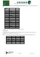
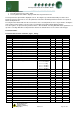
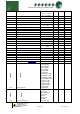
You can now set the address using the table below
Display
Option
IP-1
IP Address byte 1
IP-2
IP Address byte 2
IP-3
IP Address byte 3
IP-4
IP Address byte 4
nL
Network Mask Length
gt-1
Gateway Address byte 1
gt-2
Gateway Address byte 2
gt-3
Gateway Address byte 3
gt-4
Gateway Address byte 4
ESC
Exit network menu. N.B. this option must be
selected to save any changes made in this menu
IP-r
To configure the communication module for IP-r, set the three rotary switches to give each controller a unique
identifier (other than 000). The module should then be connected to the controller and the network via the Ethernet
port. The Data Manager will use DHCP to allocate the controller an IP address.
From the function menu select nEt
Press enter and the display will show “IP-r”, press enter
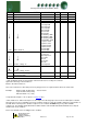
You can now view the address given by the DHCP server
IP1: Shows the first IP address value (10 in the example below)
IP2: Shows the second IP address value (1 in the example below)
IP3: Shows the third IP address value (2 in the example below)
IP4: Shows the forth IP address value (86 in the example below)
Example: 10.1.2.86