Mercury Plant Controller Installation Guide Mercury Plant - Pack Controller Installation & User Guide Product Number: PR0600 PSU: - PR0625 Warning Ensure that all power is switched off before installing or maintaining this product Please Note The specifications of the product detailed on this Set-Up Guide may change without notice. RDM Revision 2.
Mercury Plant Controller Installation Guide Contents: THE MERCURY RANGE .............................................................................................................................................4 Description ..................................................................................................................................................................4 Configuration ..........................................................................................................
Mercury Plant Controller Installation Guide Section Stages ..........................................................................................................................................................57 Alarm Relay ...............................................................................................................................................................57 Stage Sizes ..............................................................................................................
Mercury Plant Controller Installation Guide The Mercury Range From Resource Data Management This documentation refers to the controller Mercury Plant Controller Description The Mercury Plant Controller is a versatile controller intended for Pack and/or Condenser control. It has 12 relay outputs that are configurable for compressors, loaders, trim compressors or fans. The 12 digital inputs can be assigned for Pack or Condenser section inputs or general alarms.
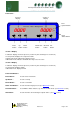
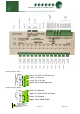
Mercury Plant Controller Installation Guide Front Panel: Section 2 Display Section 1 Display FLT1 System Alarms Resource Data Management FLT 1 FLT 2 PRESSURE 1 PRESSURE 2 FLT2 Status Alarms Enter button Up Down button button Quick view button Override Info button button Section 1 Display 4 character display, shows the pressure (suction for pack, discharge for condensers) In set-up mode, displays the set-up menu items In quick view mode, indicates the target pressure In Override mode, indicates an
Mercury Plant Controller Installation Guide Plant Controller I/O Connections Variable Analogue Inputs OUTPUTS INPUTS VARIABLE Lower orInput 0-10V dc Input Lower Tier Tier 0-5V 0-10V Upper Tier Ground Lower Tier +12 Volts Upper Tier 4-20mA loop input Variable Analogue Outputs OUTPUTS INPUTS VARIABLE Lower Tier Ground Upper Tier Tier0-5V 0-10V Upper or Output 0-10V dc Output Lower Tier Ground Upper Tier 4-20mA Ouput Warning Ensure that all power is switched off before installing or maintaining this prod
Mercury Plant Controller Installation Guide Input/s & Outputs All Types Digital Input 1 Digital Input 2 Digital Input 3 Digital Input 4 Digital Input 5 Digital Input 6 Digital Input 7 Digital Input 8 Digital Input 9 Digital Input 10 Digital Input 11 Digital Input 12 Analogue Input 1 Analogue Input 2 Analogue Input 3 Analogue Input 4 Analogue Input 5 Analogue Input 6 Analogue Input 7 Analogue Input 8 Variable Analogue Input 1 Variable Analogue Input 2 Variable Analogue Input 3 Variable Analogue Output 1 Vari
Mercury Plant Controller Installation Guide Note 2: Several probe types are available, see Probe Type Note 3: The Status LED is not present on older variants of the Plant controller hardware. If the status LED is present and the Plant controller software is V1.7 or greater then Analogue inputs 1 to 3 are configurable either as a 4-20mA input or a 0-10Vdc input. If the above criteria is not met then Analogue inputs 1 to 3 are configurable as 420mA inputs only. In software version 2.
Mercury Plant Controller Installation Guide Universal IO Setting up from controller display, navigate to the screen “Uni” and select from the following table for U-01 to U-08. This selects what the Universal IO (U-01 to U-08) can be set for. NOTE: UniIO U-01 to U-03 can only be set as Inputs, UniIO U-04 and U-05 can only be set for Outputs and UniIO U-06 to U-08 are seen in settings but are not present on the controller hardware and are for future development.
Mercury Plant Controller Installation Guide rtc. Real time clock (This will automatically synchronise on network systems) 1. 2. 3. 4. 5. 6. 7. 8. 9. 10. Use the up or down buttons to scroll through the display until the display reads “rtc” Press enter. The display will show “t-1”.
Mercury Plant Controller Installation Guide O O Note: If the units are set to C, pressure will be displayed in Bar, if units are set to F, pressure will be displayed in PSI.
Mercury Plant Controller Installation Guide Network Configuration There are two network connection options IP-L (Rotary switches set to “000”) IP-r (Rotary switches set to “***” where * is a number between 0 and 9) IP-L allows you to fix an IP address into the controller, which you would use when you are connecting the controllers onto a customer’s local area network.
Mercury Plant Controller Installation Guide PArA. Set/view parameters 1. From the function menu scroll to PArA 2. Pressing Enter while PArA is displayed will enter the parameter menu. The first parameter option will be displayed as P-01. Pressing the Up or Down button will present the other parameter options P-02, P-03 etc. See the parameter list below to find what parameter number corresponds to which actual parameter. Pressing the Enter button will show the current value of the selected parameter.
Mercury Plant Controller Installation Guide P-61 P480 P481 P482 P483 P-80 General Alarm Delay Liquid Level High Liquid Level Low Liquid Level Liquid Level Alarm Delay Status Fault 1 P-91 P100 Status Fault 12 Section 1 Stage 1 P111 P120 Section 1 Stage 12 Section 1 Stage 1 Size P131 dFLt Section 1 Stage 12 Size Restore Default Settings (Front panel Only) 00:00 – 60:00 0 = Off, 1 = On 0 - 100 0 - 100 00:00 – 99:00 (0) Unused (1) Comp N/O (2) Comp N/C (3) Cond N/O (4) Cond N/C (5) Gen N/O (6) Gen N/C (
Mercury Plant Controller Installation Guide Parameter table for Dual Pack Controller (Type 2, Fuzzy) Number P-01 P-02 P-03 P-04 P-05 P-06 P-20 P473 P-21 P-22 P-23 P-24 P-26 P442 P444 P446 P490 P492 P470 P495 P497 P-27 P-28 P-29 P-30 P-31 P-32 P-33 P-34 P448 P-40 P474 P-41 P-42 P-43 P-44 P-46 P443 Parameter Range Transducer 1 Span * -3.4 - 180 Transducer 1 Offset -3.4 - 180 Transducer 2 Span * -3.4 - 180 Transducer 2 Offset -3.4 - 180 Transducer 3 Span * -3.4 - 180 Transducer 3 Offset -3.
Mercury Plant Controller Installation Guide P445 P447 P491 P493 P471 Section 2 INV Minimum Section 2 INV Maximum Section 2 Gas Dump Section 2 Gas diff Section 2 Always Run last P496 P498 P-47 P-48 P-49 P-50 P-51 P-52 P-53 P-35 P449 Sect 2 Compressor Unload Sect 1 Equal Section 2 Response On Speed Section 2 Response Off Speed Section 2 Optimise Limit Section 2 Alarm Delay Section 2 HP Alarm Section 2 LP Alarm Section 2 LP Shut-down Section 2 Low Alarm Section 2 Fail P472 P-60 P-61 P480 P481 P482 P483 P4
Mercury Plant Controller Installation Guide P120 Section 1 Stage 1 Size P131 P140 Section 1 Stage 12 Size Section 2 Stage 1 P151 P160 Section 2 Stage 12 Section 2 Stage 1 Size P171 dFLt Section 2 Stage 12 Size Restore Default settings (Front panel Only) 0.0 – 60.0 (0) None, (1) Unused, (2) Compressor, (3) Loader, (4) Fan (5) Inverter (6) Trim (7) Comp Run 0.0 – 60.0 0.1 - 0.0 1 - 0 0.1 - 0.0 ESc * Span and Offset allows for the full range of the transducer to be used by the controller.
Mercury Plant Controller Installation Guide Parameter table for Pack/Condenser Controller (Type 3, Fuzzy) Number P-01 P-02 P-03 P-04 P-05 P-06 P-20 P473 P-21 P-22 P-23 P-24 P-26 P442 Parameter Transducer 1 Span * Transducer 1 Offset Transducer 2 Span * Transducer 2 Offset Transducer 3 Span * Transducer 3 Offset Section 1 Target Pressure Section 1 External Target Pressure Section 1 Target Pressure Above P-20 Section 1 Target Pressure Below P-20 Section 1 Starts/Hour Section 1 Run Smallest ** Section 1 Inver
Mercury Plant Controller Installation Guide P-50 P-51 P-52 P-53 P-35 P449 P450 P451 Section 2 Alarm Delay Section 2 HP Alarm Section 2 LP Alarm Section 2 LP Shut-down Section 2 Low Alarm Section 2 Fail Section 2 Sticky Fans Section 2 Night Set Back P452 P453 P454 P455 P456 P457 P458 P459 Section 2 Night Reduction Section 2 Night Set Back On Time Section 2 Night Set Back Off Time Sect 2 Night Set Back Pressure Limit Section 2 Day Reduction Section 2 Day Pressure Limit Section 2 Transducer fail Level Secti
Mercury Plant Controller Installation Guide P474 P475 P476 P472 P-60 P-61 P480 P481 P482 P483 P494 P-80 Sect 2 Ext Trgt Dis Trip Dis Diff Run Proof Status fault Delay General Alarm Delay Liquid Level High Liquid Level Low Liquid Level Liquid Level Alarm Delay Dual Standby See Standby Mode Status Fault 1 -3.4 - 180 -3.4 - 180 -3.
Mercury Plant Controller Installation Guide Example: Danfoss AKS 33 with range: -1 bar to 12 bar Span would be 190 (13 bar) Offset would be -15 (-1 bar) **Run smallest = on : - When all compressors are off (because the target pressure has been satisfied) the controller, when the pressure rises, will always turn on the smallest compressor after the variable output has reached 100%.
Mercury Plant Controller Installation Guide Parameter table for Dual Condenser Controller (Type 4, Fuzzy) Number P-01 P-02 P-03 P-04 P-05 P-06 P-20 P-21 P-22 P-26 P442 Parameter Transducer 1 Span * Transducer 1 Offset Transducer 2 Span * Transducer 2 Offset Transducer 3 Span * Transducer 3 Offset Section 1 Target Pressure Section 1 Target Pressure Above P-20 Section 1 Target Pressure Below P-20 Section 1 Inverter Section 1 INV Bypass P444 P446 P-27 P-28 P-30 P-31 P-32 P-33 P-34 P448 P400 P401 Section 1
Mercury Plant Controller Installation Guide P411 Section 1 Drop select P414 P415 P416 P417 P418 P419 P420 P421 P422 P438 Section 1 Pressure at 0 C/32 F O O Section 1 Pressure at 10 C/50 F O O Section 1 Pressure at 20 C/68 F O O Section 1 Pressure at 30 C/86 F O O Section 1 Pressure at 40 C/104 F O O Section 1 Pressure at 50 C/122 F Section 1 Low Limit Section 1 High Limit Section 1 Condenser offset Section 1 Split P430 P432 P434 P436 P440 Section 1 Split Temp Section 1 Split Temp Diff Sect 1 Split Pres
Mercury Plant Controller Installation Guide P452 P453 P454 P455 P456 P457 P458 P459 Section 2 Night Reduction Section 2 Night Set Back On Time Section 2 Night Set Back Off Time Section 2 Night Set Back Pressure Limit Section 2 Day Reduction Section 2 Day Pressure Limit Section 2 Transducer fail Level Section 2 Control Type P460 Section 2 Float Select P412 Section 2 Drop Select P461 P462 P463 P464 P465 P466 P467 P468 P469 P439 Section 2 Pressure at 0 C/32 F O O Section 2 Pressure at 10 C/50 F O O Sect
Mercury Plant Controller Installation Guide P494 P-80 Dual Standby See Standby Mode Status Fault 1 P-91 P100 Status Fault 12 Section 1 Stage 1 P111 P140 Section 1 Stage 12 Section 2 Stage 1 P151 DFLt Section 2 Stage 12 Restore Default Settings (Front panel Only) 0 = Off, 1 = On (0) Unused (1) Comp N/O (2) Comp N/C (3) Cond N/O (4) Cond N/C (5) Gen N/O (6) Gen N/C (7) Standby 1 N/O (8) Standby 1 N/C (9) Standby 2 N/O (10) Standby 2N/C (11) Run 1 N/O (12) Run 1 N/C (13) Run 2 N/O (14) Run 2 N/C (15) I
Mercury Plant Controller Installation Guide Parameter table for Condenser Controller (Type 5, Fuzzy) Number P-01 P-02 P-03 P-04 P-05 P-06 P-20 P-21 P-26 P442 Parameter Transducer 1 Span * Transducer 1 Offset Transducer 2 Span * Transducer 2 Offset Transducer 3 Span * Transducer 3 Offset Section 1 Target Pressure Section 1 Target Pressure Above P-20 Section 1 Target Pressure Below P-20 Section 1 Inverter Section 1 INV Bypass P444 P446 P-27 P-28 P-30 P-31 P-32 P-33 P-34 P448 P400 P401 Section 1 INV Minim
Mercury Plant Controller Installation Guide P411 Section 1 Drop select P414 P415 P420 P421 P422 P438 P430 P432 P434 P436 P440 Section 1 Pressure at 0 C/32 F Section 1 Pressure at O O 10 C/50 F Section 1 Pressure at O O 20 C/68 F Section 1 Pressure at O O 30 C/86 F Section 1 Pressure at O O 40 C/104 F Section 1 Pressure at O O 50 C/122 F Section 1 Low Limit Section 1 High Limit Section 1 Condenser offset Section 1 Split Section 1 Split Temp Section 1 Split Temp Diff Sect 1 Split Press Sect 1 Split Press
Mercury Plant Controller Installation Guide P100 Section 1 Stage 1 P111 dFLt Section 1 Stage 12 Restore Default Settings (Front panel Only) (0) None, (1) Unused, (2) Compressor, (3) Loader, (4) Fan (5) Inverter (6) Trim (7) Comp Run 1 - 0 ESc * Span and Offset allows for the full range of the transducer to be used by the controller. Span is the full range of the transducer Offset is the value below zero. Note.
Mercury Plant Controller Installation Guide Parameter table for Pack Controller (Type 6, Staged) Number P-01 P-02 P-03 P-04 P-05 P-06 P-20 P473 P-21 P-22 P-23 P-24 P-25 P-26 P442 P444 P446 P490 P492 P470 P-27 P-28 P-29 P-30 P-31 P-32 P-33 P-34 P448 P472 P-60 P-61 P480 P481 P482 P483 Parameter Range Transducer 1 Span * -3.4 - 180 Transducer 1 Offset -3.4 - 180 Transducer 2 Span * -3.4 - 180 Transducer 2 Offset -3.4 - 180 Transducer 3 Span * -3.4 - 180 Transducer 3 Offset -3.
Mercury Plant Controller Installation Guide P-80 Status Fault 1 P-91 P100 Status Fault 12 Section 1 Stage 1 Relay 1 P111 P112 Section 1 Stage 1 Relay 12 Section 1 Stage 2 Relay 1 P123 P124 Section 1 Stage 2 Relay 12 Section 1 Stage 3 Relay 1 P135 P136 Section 1 Stage 3 Relay 12 Section 1 Stage 4 Relay 1 P147 P148 Section 1 Stage 4 Relay 12 Section 1 Stage 5 Relay 1 P159 P160 Section 1 Stage 5 Relay 12 Section 1 Stage 6 Relay 1 P171 P172 Section 1 Stage 6 Relay 12 Section 1 Stage 7 Relay 1 P1
Mercury Plant Controller Installation Guide P196 Section 1 Stage 9 Relay 1 P207 P208 Section 1 Stage 9 Relay 12 Section 1 Stage 10 Relay 1 P219 P220 Section 1 Stage 10 Relay 12 Section 1 Stage 11 Relay 1 P231 P232 Section 1 Stage 11 Relay 12 Section 1 Stage 12 Relay 1 P243 dFLt Section 1 Stage 12 Relay 12 Restore Default Settings (Front panel Only) 0 = off 1 = on 1 - 0 0 = off 1 = on 1 - 0 0 = off 1 = on 1 - 0 0 = off 1 = on 1 - 0 ESc * Span and Offset allows for the full range of
Mercury Plant Controller Installation Guide Parameter table for Dual Pack Controller (Type 7, Staged) Number P-01 P-02 P-03 P-04 P-05 P-06 P-20 P473 P-21 P-22 P-23 P-24 P-25 P-26 P442 P444 P446 P490 P492 P470 P-27 P-28 P-29 P-30 P-31 P-32 P-33 P-34 P448 P-40 P474 P-41 P-42 P-43 P-44 P-45 P-46 P443 Parameter Range Transducer 1 Span * -3.4 - 180 Transducer 1 Offset -3.4 - 180 Transducer 2 Span * -3.4 - 180 Transducer 2 Offset -3.4 - 180 Transducer 3 Span * -3.4 - 180 Transducer 3 Offset -3.
Mercury Plant Controller Installation Guide P445 P447 P491 P493 P471 P-47 P-48 P-49 P-50 P-51 P-52 P-53 P-35 P449 P472 P-60 P-61 P480 P481 P482 P483 P494 P-80 Section 2 INV Minimum Section 2 INV Maximum Section 2 Gas Dump Section 2 Gas diff Section 2 Always Run last Section 2 Response On Speed Section 2 Response Off Speed Section 2 Optimise Limit Section 2 Alarm Delay Section 2 HP Alarm Section 2 LP Alarm Section 2 LP Shut-down Section 2 Low Alarm Section 2 Fail Run Proof Status fault Delay General Alarm D
Mercury Plant Controller Installation Guide P136 Section 1 Stage 4 Relay 1 P147 P148 Section 1 Stage 4 Relay 12 Section 1 Stage 5 Relay 1 P159 P160 Section 1 Stage 5 Relay 12 Section 1 Stage 6 Relay 1 P171 P172 Section 1 Stage 6 Relay 12 Section 1 Stage 7 Relay 1 P183 P184 Section 1 Stage 7 Relay 12 Section 1 Stage 8 Relay 1 P195 P196 Section 1 Stage 8 Relay 12 Section 1 Stage 9 Relay 1 P207 P208 Section 1 Stage 9 Relay 12 Section 1 Stage 10 Relay 1 P219 P220 Section 1 Stage 10 Relay 12 Secti
Mercury Plant Controller Installation Guide P268 Section 2 Stage 3 Relay 1 P279 P280 Section 2 Stage 3 Relay 12 Section 2 Stage 4 Relay 1 P291 P292 Section 2 Stage 4 Relay 12 Section 2 Stage 5 Relay 1 P303 P-304 Section 2 Stage 5 Relay 12 Section 2 Stage 6 Relay 1 P315 P316 Section 2 Stage 6 Relay 12 Section 2 Stage 7 Relay 1 P327 P328 Section 2 Stage 7 Relay 12 Section 2 Stage 8 Relay 1 P339 P340 Section 2 Stage 8 Relay 12 Section 2 Stage 9 Relay 1 P351 P352 Section 2 Stage 9 Relay 12 Sectio
Mercury Plant Controller Installation Guide Parameter table for Pack/Condenser Controller (Type 8, Staged) Number P-01 P-02 P-03 P-04 P-05 P-06 P-20 P473 P-21 P-22 P-23 P-24 P-25 P-26 P442 Parameter Transducer 1 Span * Transducer 1 Offset Transducer 2 Span * Transducer 2 Offset Transducer 3 Span * Transducer 3 Offset Section 1 Target Pressure Section 1 External Target Pressure Section 1 Target Pressure Above P-20 Section 1 Target Pressure Below P-20 Section 1 Number of Stages Section 1 Stage-on Delay Sect
Mercury Plant Controller Installation Guide P447 P-47 P-48 P-50 P-51 P-52 P-53 P-35 P449 P450 P451 Section 2 INV Maximum Section 2 Response On Speed Section 2 Response Off Speed Section 2 Alarm Delay Section 2 HP Alarm Section 2 LP Alarm Section 2 LP Shut-down Section 2 Low Alarm Section 2 Fail Section 2 Sticky Fans Section 2 Night Set Back P452 P453 P454 P455 P456 P457 P458 P459 Section 2 Night Reduction Section 2 Night Set Back On Time Section 2 Night Set Back Off Time Section 2 Night Set Back Pressure
Mercury Plant Controller Installation Guide P435 P437 P441 Sect 2 Split Press Sect 2 Split Press Diff Sect 2 Heat reclaim P474 P475 P476 P472 P-60 P-61 P480 P481 P482 P483 P494 P-80 Sect 2 Ext Trgt Dis Trip Dis Diff Run Proof Status fault Delay General Alarm Delay Liquid Level High Liquid Level Low Liquid Level Liquid Level Alarm Delay Dual Standby See Standby Mode Status Fault 1 P-91 P100 Status Fault 12 Section 1 Stage 1 Relay 1 P111 P112 Section 1 Stage 1 Relay 12 Section 1 Stage 2 Relay 1 P123 P
Mercury Plant Controller Installation Guide P136 Section 1 Stage 4 Relay 1 P147 P148 Section 1 Stage 4 Relay 12 Section 1 Stage 5 Relay 1 P159 P160 Section 1 Stage 5 Relay 12 Section 1 Stage 6 Relay 1 P171 P172 Section 1 Stage 6 Relay 12 Section 1 Stage 7 Relay 1 P183 P184 Section 1 Stage 7 Relay 12 Section 1 Stage 8 Relay 1 P195 P196 Section 1 Stage 8 Relay 12 Section 1 Stage 9 Relay 1 P207 P208 Section 1 Stage 9 Relay 12 Section 1 Stage 10 Relay 1 P219 P220 Section 1 Stage 10 Relay 12 Secti
Mercury Plant Controller Installation Guide Parameter table for Dual Condenser Controller (Type 9, Staged) Number P-01 P-02 P-03 P-04 P-05 P-06 P-20 P-21 P-22 P-23 P-24 P-25 P-26 P442 Parameter Transducer 1 Span * Transducer 1 Offset Transducer 2 Span * Transducer 2 Offset Transducer 3 Span * Transducer 3 Offset Section 1 Target Pressure Section 1 Target Pressure Above P-20 Section 1 Target Pressure Below P-20 Section 1 Number of Stages Section 1 Stage-on Delay Section 1 Stage-off Delay Section 1 Inverter
Mercury Plant Controller Installation Guide P411 Section 1 Drop select P414 P415 P416 P417 P418 P419 P420 P421 P422 P438 Section 1 Pressure at 0 C/32 F O O Section 1 Pressure at 10 C/50 F O O Section 1 Pressure at 20 C/68 F O O Section 1 Pressure at 30 C/86 F O O Section 1 Pressure at 40 C/104 F O O Section 1 Pressure at 50 C/122 F Section 1 Low Limit Section 1 High Limit Section 1 Condenser offset Section 1 Split P430 P432 P434 P436 P440 Section 1 Split Temp Section 1 Split Temp Diff Sect 1 Split Pre
Mercury Plant Controller Installation Guide P-53 P-35 P-449 P450 P451 Section 2 LP Shut-down Section 2 Low Alarm Section 2 Fail Section 2 Sticky Fans Section 2 Night Set Back P452 P453 P454 P455 P456 P457 P458 P459 Section 2 Night Reduction Section 2 Night Set Back On Time Section 2 Night Set Back Off Time Section 2 Night Set Back Pressure Limit Section 2 Day Reduction Section 2 Day Pressure Limit Section 2 Transducer fail Level Section 2 Control Type P460 Section 2 Float Select P412 Section 2 Drop S
Mercury Plant Controller Installation Guide P-60 P-61 P480 Status fault Delay General Alarm Delay Liquid Level P481 P482 P483 P494 P-80 High Liquid Level Low Liquid Level Liquid Level Alarm Delay Dual Standby See Standby Mode Status Fault 1 P-91 dFLt Status Fault 12 Restore Default Settings (Front panel Only) 00:00 – 60:00 00:00 – 60:00 0 = Off 1 = On 0 - 100 0 - 100 00:00 – 99:00 0 = Off, 1 = On (0) Unused (1) Comp N/O (2) Comp N/C (3) Cond N/O (4) Cond N/C (5) Gen N/O (6) Gen N/C (7) Standby 1 N/O (
Mercury Plant Controller Installation Guide Parameter table for Condenser Controller (Type 10, Staged) Number P-01 P-02 P-03 P-04 P-05 P-06 P-20 P-21 P-22 P-23 P-24 P-25 P-26 P442 Parameter Transducer 1 Span * Transducer 1 Offset Transducer 2 Span * Transducer 2 Offset Transducer 3 Span * Transducer 3 Offset Section 1 Target Pressure Section 1 Target Pressure Above P-20 Section 1 Target Pressure Below P-20 Section 1 Number of Stages Section 1 Stage-on Delay Section 1 Stage-off Delay Section 1 Inverter Sec
Mercury Plant Controller Installation Guide P411 Section 1 Drop select P414 P415 P416 P417 P418 P419 P420 P421 P422 P438 P430 P432 P434 P436 P440 Section 1 Pressure at 0 C/32 F O O Section 1 Pressure at 10 C/50 F O O Section 1 Pressure at 20 C/68 F O O Section 1 Pressure at 30 C/86 F O O Section 1 Pressure at 40 C/104 F O O Section 1 Pressure at 50 C/122 F Section 1 Low Limit Section 1 High Limit Section 1 Condenser offset Section 1 Split Section 1 Split Temp Section 1 Split Temp Diff Sect 1 Split Press
Mercury Plant Controller Installation Guide * Span and Offset allows for the full range of the transducer to be used by the controller. Span is the full range of the transducer Offset is the value below zero. Note. The controller uses absolute pressure; if gauge pressure is required, add +1 Bar to the offset value. Example: Danfoss AKS 33 with range: -1 bar to 12 bar Span would be 190 (13 bar) Offset would be -15 (-1 bar) If only transducer input 1 in use please see Note 10 also.
Mercury Plant Controller Installation Guide P-28/48 Response Off Speed P-29/49 Optimise Limit P-30/50 P-31/51 P-32/52 P-33/53 P-34/35 Alarm Delay HP Alarm LP Alarm LP Shut-down Low Alarm P448/449 Sect 1 / 2 Fail P400/450 Sticky Fans P401/451 Night Set Back Allows the user to speed up/slow down the stage off speed (Option: - 1 to 60 with 60 being fastest response) Note: This parameter applies to the inverter output only when using any of the Staged types.
Mercury Plant Controller Installation Guide P406/456 Day Reduction P407/457 Day Pressure Limit P408/458 P409/459 Transducer fail Level Control Type Reduces the inverter output by this amount when the timer is not in its night zone. Pressure set-point to disable the day reduction feature. Day reduction is disabled above this level and enabled below it. Sets the output level of the inverter if the transducer fails Selects between Fixed, Floating or Drop Leg control for Condenser control only.
Mercury Plant Controller Installation Guide P475 Discharge trip P476 Discharge Trip Diff P472 P-60 P-61 P480 Run Proof Status fault Delay General Alarm Delay Liquid Level P481/482 Liquid Level Alarm P483 Liquid Level Alarm Delay P494 Dual Standby P-80 Status Fault 1 1 = On (Uses Ext Set Point) 2 = On Rly(Uses Ext Set Point and allocates a Relay) If Discharge Pressure exceeds this setting All compressors go off immediately and all fans come on immediately. A Discharge Trip Alarm is generated.
Mercury Plant Controller Installation Guide To reset the run proof for any stage, after maintenance, and return a compressor back into the control strategy use the menu item Override. The override option is used to manually turn on the compressor output. If the proof signal is returned within the allotted time delay the compressor is allocated back into the control strategy; if the proof isn’t returned the compressor relay will go off and remain out of the control strategy.
Mercury Plant Controller Installation Guide Example 2 (Type 1 Fuzzy) Pack set up: 2 compressors with 2 Loaders each Sect 1 stage 1 = Comp. Sect 1 stage 2 = Loader. Sect 1 stage 4 = Comp. Sect 1 stage 5 = Loader. Parameter P495 = 1 (On) Sect 1 stage 3 = Loader. Sect 1 stage 6 = Loader. Switching On sequence: Pressure above set point + diff First compressor comes on. First compressor loader 1 comes on. First compressor loader 2 comes on. Second compressor comes on. Second compressor loader 1 comes on.
Mercury Plant Controller Installation Guide An “INV Bypass” alarm will be generated. Note if the inverter run signal is not returned within the allotted time in the first instance but is successful in the second, third or fourth attempt (Depending on (P442/443) then any future inverter run tests must still complete all tests. To reinstate the inverter output, once the fault has been rectified, either reset the Plant controller or by using the Override feature force the relay associated to the inverter on.
Mercury Plant Controller Installation Guide Plant Controller home page Log in using an appropriate username and password; setup operations can then be used via the PC by clicking on the appropriate link: - Link Values Settings Alarm Log Graph Set Parameters System Log Network Time Reset Configuration Export Log Save Pack Setup Load pack Setup Clear Alarm Log Version Operation Shows the values being return on the controllers inputs and outputs Shows the controllers parameter settings Shows the controlle
Mercury Plant Controller Installation Guide Change Configuration (PC) This page allows the user to change the configuration of the Pack controller: - 1 example as follows:- Change Parameters (PC) Warning Ensure that all power is switched off before installing or maintaining this product Please Note The specifications of the product detailed on this Set-Up Guide may change without notice. RDM Revision 2.
Mercury Plant Controller Installation Guide Configuration of inputs and outputs: Status Inputs Section Inputs can be set up as: 0 1 2 3 4 5 6 7 Unused Compressor Normally Open Compressor Normally Closed Condenser Normally Open Condenser Normally Closed General Normally Open General Normally Closed Standby 1 Normally Open 8 Standby 1 Normally Closed 9 Standby 2 Normally Open 10 Standby 2 Normally Closed 11 Run 1 Normally Open 12 Run 1 Normally Closed 13 Run 2 Normally Open 14 Run 2 Normally Cl
Mercury Plant Controller Installation Guide External Target Pack Controller To use Sect 1/2 Ext Target (P473/474) instead of Section 1/2 Target Pressure (P-20/40) a status Input must be set to “Run 1/2 N/O or N/C”. When the input is activated the Target Pressure will change from (P-20/40) to (P473/474) When the input is de-activated the Target Pressure will revert back to (P-20/40) Condenser Controller Heat Reclaim must be set to “On” or “On/Rly”.
Mercury Plant Controller Installation Guide Relay Outputs – Configuration Compressor(s)/Loader(s)/Fan(s) relays are assigned using the Stage parameters for a given section. Additional relay outputs for a section will be assigned in the following order once the Stage parameters have been configured.
Mercury Plant Controller Installation Guide Operation (Fuzzy) Once the controller has been set-up and configured, normal operation will resume. If the appropriate Type has been selected the controller will operate using a “fuzzy logic” based control algorithm. The controller will determine the stages to bring on and off using the fuzzy logic rules and adhering to the starts/hr criteria.
Mercury Plant Controller Installation Guide Other operational features Floating Head Pressure When the condenser controller is used in the “Floating Head pressure” mode, the temperature to pressure parameters must be used to profile a pressure curve from the air on temperature probe for the condenser (P414 to P419 and P461 to P466). The value read from the temperature probe is added to a “Condenser Offset” (P422) and then converted to a pressure.
Mercury Plant Controller Installation Guide Invert Relays The operation of the relays can be inverted so that N/C contacts can be used for energisation. This can be done from the configure screen on web page. Choose the relay(s) you wish to invert and set them to on. This process can also be completed from the controller display. Navigate to the menu option rly and select the relay output you wish to invert for example r-05 is relay output 5.
Mercury Plant Controller Installation Guide Viewing Inputs and Outputs Apart from setting up the controller, you can also view the status of the inputs and outputs. 1. From the function menu, select “IO”, press enter 2. You can now scroll through the IO tables as set out below. The tables you view will depend on the controller type configuration.
Mercury Plant Controller Installation Guide Input/Output table for Dual Pack Controller (Type 2) Number I-01 I-02 I-03 I-10 IO Pressure Input 1 Pressure Input 2 Pressure Input 3 Analogue Input 1 I-17 I-30 Analogue Input 8 Digital Input 1 I-41 I-50 Digital Input 12 Section 1 Run I-51 Section 2 Run I-54 O-01 Liquid Level Relay 1 O-12 O-31 O-32 O-41 O-42 O-70 O-71 O-72 O-73 S-01 Relay 12 Variable Output 1 Variable Output 2 Optimisation Level Pack 1 Optimisation Level Pack 2 Sect 1 Bypass Sect 2 Byp
Mercury Plant Controller Installation Guide Input/Output table for Pack/Condenser Controller (Type 3) Number I-01 I-02 I-03 I-10 IO Pressure Input 1 Pressure Input 2 Pressure Input 3 Analogue Input 1 Range -3.4 - 180 -3.4 - 180 -3.
Mercury Plant Controller Installation Guide S-02 Section 1 Control States (0) Stabilise (1) Initial (2) Normal (3) High Pressure (4) Low Pressure (5) Low Shut-down (6) Transducer Fail (7) Stand-by Warning Ensure that all power is switched off before installing or maintaining this product Please Note The specifications of the product detailed on this Set-Up Guide may change without notice. RDM Revision 2.
Mercury Plant Controller Installation Guide Input/Output table for Dual Condenser Controller (Type 4) Number I-01 I-02 I-03 I-10 IO Pressure Input 1 Pressure Input 2 Pressure Input 3 Analogue Input 1 I-17 I-20 I-21 I-22 I-23 I-30 Analogue Input 8 Sect 1 rem float Sect 2 rem Float Sect 1 Rem Drop Leg Sect 2 Rem drop Leg Digital Input 1 I-41 I-52 Digital Input 12 Sect 1 Heat I-53 Sect 2 Heat I-54 I-55 I-56 O-01 Liquid Level Rem Ext 1 Rem Ext 2 Relay 1 O-12 O-31 O-32 O-51 O-52 O-53 O-54 O-55 O-56 O
Mercury Plant Controller Installation Guide S-01 Section 1 Control States S-02 Section 1 Control States (0) Stabilise (1) Initial (2) Normal (3) High Pressure (4) Low Pressure (5) Low Shut-down (6) Transducer Fail (7) Stand-by (0) Stabilise (1) Initial (2) Normal (3) High Pressure (4) Low Pressure (5) Low Shut-down (6) Transducer Fail (7) Stand-by Warning Ensure that all power is switched off before installing or maintaining this product Please Note The specifications of the product detailed on this S
Mercury Plant Controller Installation Guide Input/Output table for Condenser Controller (Type 5) Number I-01 I-02 I-03 I-10 IO Pressure Input 1 Pressure Input 2 Pressure Input 3 Analogue Input 1 I-17 I-20 I-22 I-30 Analogue Input 8 Sect 1 rem float Sect 1 Rem Drop Leg Digital Input 1 I-41 I-52 Digital Input 12 Sect 1 Heat I-54 I-55 O-01 Liquid Level Rem Ext 1 Relay 1 O-12 O-31 O-51 O-53 O-55 O-57 O-59 O-61 Relay 12 Variable Output 1 Section 1 Float Pressure Sect 1 Drop Leg Temp Sect 1 Drop Leg Pre
Mercury Plant Controller Installation Guide Input/Output table for Pack Controller (Type 6) Number I-01 I-02 I-03 I-10 IO Pressure Input 1 Pressure Input 2 Pressure Input 3 Analogue Input 1 I-17 I-30 Analogue Input 8 Digital Input 1 I-41 I-50 Digital Input 12 Section 1 Run I-54 O-01 Liquid Level Relay 1 O-12 O-20 O-31 O-41 O-70 O-72 S-01 Relay 12 Section 1 Stage Variable Output 1 Optimisation Level Sect 1 Bypass Section 1 Gas Dump Section 1 Control States Range -3.4 - 180 -3.4 - 180 -3.
Mercury Plant Controller Installation Guide Input/Output table for Dual Pack Controller (Type 7) Number I-01 I-02 I-03 I-10 IO Pressure Input 1 Pressure Input 2 Pressure Input 3 Analogue Input 1 I-17 I-30 Analogue Input 8 Digital Input 1 I-41 I-50 Digital Input 12 Section 1 Run I-51 Section 2 Run I-54 O-01 Liquid Level Relay 1 O-12 O-20 O-21 O-31 O-32 O-41 O-42 O-70 O-71 O-72 O-73 S-01 Relay 12 Section 1 Stage Section 2 Stage Variable Output 1 Variable Output 2 Optimisation Level Pack 1 Optimisa
Mercury Plant Controller Installation Guide Input/Output table for Pack/Condenser Controller (Type 8) Number I-01 I-02 I-03 I-10 IO Pressure Input 1 Pressure Input 2 Pressure Input 3 Analogue Input 1 I-17 I-21 I-23 I-30 Analogue Input 8 Sect 2 rem Float Sect 2 Rem drop Leg Digital Input 1 I-41 I-50 Digital Input 12 Section 1 Run I-53 Sect 2 Heat I-54 I-56 O-01 Liquid Level Rem Ext 2 Relay 1 O-12 O-20 O-21 O-31 O-32 O-41 O-52 O-54 O-56 O-58 O-60 O-62 O-64 O-70 O-71 O-72 S-01 Relay 12 Section 1 St
Mercury Plant Controller Installation Guide S-02 Section 1 Control States (0) Stabilise (1) Initial (2) Normal (3) High Pressure (4) Low Pressure (5) Low Shut-down (6) Transducer Fail (7) Stand-by Warning Ensure that all power is switched off before installing or maintaining this product Please Note The specifications of the product detailed on this Set-Up Guide may change without notice. RDM Revision 2.
Mercury Plant Controller Installation Guide Input/Output table for Dual Condenser Controller (Type 9) Number I-01 I-02 I-03 I-10 IO Pressure Input 1 Pressure Input 2 Pressure Input 3 Analogue Input 1 I-17 I-20 I-21 I-22 I-23 I-30 Analogue Input 8 Sect 1 rem float Sect 2 rem Float Sect 1 Rem Drop Leg Sect 2 Rem drop Leg Digital Input 1 I-41 I-52 Digital Input 12 Sect 1 Heat I-53 Sect 2 Heat I-54 I-55 I-56 O-01 Liquid Level Rem Ext 1 Rem Ext 2 Relay 1 O-12 O-20 O-21 O-31 O-32 O-51 O-52 O-53 O-54 O-
Mercury Plant Controller Installation Guide S-01 Section 1 Control States S-02 Section 1 Control States (0) Stabilise (1) Initial (2) Normal (3) High Pressure (4) Low Pressure (5) Low Shut-down (6) Transducer Fail (7) Stand-by (0) Stabilise (1) Initial (2) Normal (3) High Pressure (4) Low Pressure (5) Low Shut-down (6) Transducer Fail (7) Stand-by Warning Ensure that all power is switched off before installing or maintaining this product Please Note The specifications of the product detailed on this S
Mercury Plant Controller Installation Guide Input/Output table for Condenser Controller (Type 10) Number I-01 I-02 I-03 I-10 IO Pressure Input 1 Pressure Input 2 Pressure Input 3 Analogue Input 1 I-17 I-20 I-22 I-30 Analogue Input 8 Sect 1 rem float Sect 1 Rem Drop Leg Digital Input 1 I-41 I-52 Digital Input 12 Sect 1 Heat I-54 I-55 O-01 Liquid Level Rem Ext 1 Relay 1 O-12 O-20 O-31 O-51 O-53 O-55 O-57 O-59 O-61 O-63 O-70 S-01 Relay 12 Section 1 Stage Variable Output 1 Section 1 Float Pressure Sec
Mercury Plant Controller Installation Guide Quickview Pressing the “quickview” button during normal operation displays the target pressure. If a two-stage controller has been configured, both target pressures are displayed on the corresponding Section display. Press the “quickview” button again to go back to the normal display or wait for the time-out period to elapse. Override The override function allows the user to switch output stages on or off.
Mercury Plant Controller Installation Guide Probe Offsets Each probe input, displayed as C-01 to C-08 from the controller display menu, can have an offset applied; O O Up to ± 20 C in increments of 0.1 C. Display Messages The following messages can appear on the display during normal operation.
Mercury Plant Controller Installation Guide Specification Power requirements: Supply Voltage Range: Supply Frequency: Maximum supply current: Class 2 Insulation: 24 Vac ±10% or 24 Vdc ±10% 50 – 60 Hz ±10% <1 Amp Typical supply current: <1.0 Amp No protective Earth is required. A functional earth can be connected if the equipment is located in an electrically noisy environment. Note : The use of centre tapped to earth transformers is not allowed.
Mercury Plant Controller Installation Guide Installation: Mounting on to a DIN rail Clearances: The controller must have 10mm clearance above the top and 15mm clearance from the sides. Clearance at the front and rear is dependent on the site wiring. There is no requirement for forced cooling ventilation Cleaning: Do not wet the controller when cleaning. Clean the front by wiping with a slightly damped lint free cloth.
Mercury Plant Controller Installation Guide Appendix 1 Typical Transducer Connection For 4-20mA type transducers the diagram below shows the connections to the Plant Controller: - Connection diagram for 4-20mA transducer with 12V dc loop and from a remote device Note: The Earth connection on the transducer is not necessary unless in an electrically noisy environment.
Mercury Plant Controller Installation Guide E 24 0 V V RLY 9 RLY 7 RLY 8 NETWORK ADDRESS GROUNDS RLY 6 RLY 5 RLY 4 RL Y 3 Once the modem is satisfactorily positioned, re-assemble the Plant controller. ANALOGUE INPUTS 4. USB HOST 1&2 The orientation when fitting the modem is as follows: Identify the corner of the PCB that has only two pins. The 2 pins fit into the bottom-left position. USB DEVICE 3. 1 Before removing the modem from its' packaging, make sure that you are static free.
Mercury Plant Controller Installation Guide Appendix 3 – Supply & Status Input Wiring Appendix three applies to earlier versions of the Plant controller hardware. Connection of the supply voltage and status inputs is important so that the internal bridge rectifier is not damaged. The diagram below shows possible methods of correctly wiring the supply and status inputs. Method 1.
Mercury Plant Controller Installation Guide Appendix 4 – Supply & Status Input Wiring Appendix four applies to the current version of the Plant controller hardware. Method 1. Uses the 24Vac of the transformer supplying the input voltage; which is returned via a switch (or relay) to the status input signal line. No 0V is required at the status connector. Method 2. Uses a 0V return (from the status connector) to the status signal input. Method 3.
Mercury Plant Controller Installation Guide Revision History Revision 2.7 Date 27/05/2011 Changes Current Issue Warning Ensure that all power is switched off before installing or maintaining this product Please Note The specifications of the product detailed on this Set-Up Guide may change without notice. RDM Revision 2.