
User guide


Revision 2.2 Page 7 of 17
Warning
Please Note
The specifications of the product detailed on this
Set-Up Guide may change without notice. RDM
Ltd. shall not be liable for errors or for incidental
or consequential damages, directly and indirectly,
in connection with the furnishing, performance or
misuse of this product or document.
Ensure that all power is
switched off before
installing or maintaining
this product
ML Twin Controller Installation Guide
www.resourcedm.com
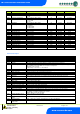
No.
Parameter
Description
P-45
Defrost Time
Defrost duration, unless terminated by P-44
P-46
Defrost Type
Defrost type, (Gas type keeps the Comp relay/s active).
P-47
Drain Down Time
A period after defrost to allow the draining of any surplus water
P-48
Recovery Time
Recovery time after defrost, OT alarms are inhibited for this period
P-49
Fan Delay Time
Fans remain off until this time has elapsed or fan delay temperature is reached
P-50
Fans in Defrost
Fans on or off during defrost; if set to on, they go off at the drain down state and come on after the
fan delay
P-51
Fan Delay Temperature
Fans stay off until this temperature is reached by the Air Off Probe or the fan delay time expires.
P-98
Lights Control
Off : Feature not used.
Case Off : Places controller in to Case Off Mode when Lights timer is in the off state.
Sec : Controller operates from a second offset (P-81) when the lights timer is in off period.
See Case Off/Secondary Setpoint
P-81
Sec Offset
Secondary Offset associated to P-98.
See Case Off/Secondary Setpoint
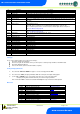
P-60
Lights Mode
local : Use the local schedule below. (P-61 - P-74)
Remote : Uses a front-end GP timer.
P-61
Sunday On Time
Sunday On Time
P-62
Sunday Off Time
Sunday Off Time
P-63
Monday On Time
Monday On Time
P-64
Monday Off Time
Monday Off Time
P-65
Tuesday On Time
Tuesday On Time
P-66
Tuesday Off Time
Tuesday Off Time
P-67
Wednesday On Time
Wednesday On Time
P-68
Wednesday Off Time
Wednesday Off Time
P-69
Thursday On Time
Thursday On Time
P-70
Thursday Off Time
Thursday Off Time
P-71
Friday On Time
Friday On Time
P-72
Friday Off Time
Friday Off Time
P-73
Saturday On Time
Saturday On Time
P-74
Saturday Off Time
Saturday Off Time
Dflt
Sets all parameters to their default value
Setting-up
Access to the controller settings can be achieved several ways,
Through the display mounted buttons
Direct access by PC into the RS232 comms. port. This requires a software package available on the RDM website
Through the RDM Data Manager.
Across an IP network. (Current controller IP address required)
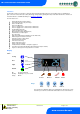
Viewing/Changing Menu Items
1. Press and hold "ENT" and "DOWN" for approx 3 seconds the display will read "EnT"
2. Press and release "ENT", the display will indicate "IO" This is the inputs and outputs viewing option
3. Use the "UP" or "DOWN" keys to cycle round the menu items, press enter at the desired item.
. Example: pressing enter at “PARA” will allow you to view or change parameters
Note. If menu item "ESC" is entered the controller will escape the set up and revert to normal operation
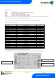
Menu Items
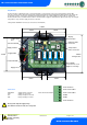
IO
Displays the inputs and outputs
Inputs and Outputs
PArA
View and change parameters
Set view parameters
Unit
Change the Units (Probe Type)
Set view units
diSP
Change the display
Display
tyPE
View Controller type
Type
Id
Enter an ID (For IP-L Use)
Set view ID
Rtc
Real Time Clock
Real Time Clock
Net
Change the network settings
Network Configuration
hub
Selects Hub/Switch (Mercury or ML)
Hub/Switch Type
SoFt
View the software version
OFSt
Probe Offsets
Probe Offset
rly1
Inverts the operation of Relay 1
Invert Relay 1
ESC
Escape back to normal operation