
User guide


Revision 2.2 Page 12 of 17
Warning
Please Note
The specifications of the product detailed on this
Set-Up Guide may change without notice. RDM
Ltd. shall not be liable for errors or for incidental
or consequential damages, directly and indirectly,
in connection with the furnishing, performance or
misuse of this product or document.
Ensure that all power is
switched off before
installing or maintaining
this product
ML Twin Controller Installation Guide
www.resourcedm.com
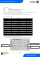
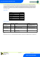
SoFt (Software version)
Press “Enter” at this display to show the software version.
OFSt
Probe offsets: - select a channel (1 - 4) and select an offset +/- 20
O
C (68
O
F)
rLY1
Inverts the operation of relay 1 so that the N/O contact can be used.
ESC
Press enter at this display to quit out of the menu.
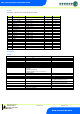
Front Panel messages:
Typical Front Panel messages: -
Display Message
System status
Ft
Control Fault
Prb1
Probe 1 Fault
Prb2
Probe 2 Fault
Prb3
Probe 3 Fault
Prb4
Probe 4 Fault
rec
Control State in Recovery
dEF
Control Sate in Defrost
AL
Control State in Alarm (Over or Under Temperature)
OFF
Controller in Case Off
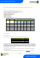
Operation:
Lead and Lag Compressor Cut-in
The Lead compressor will come on when the control temperature reaches Lead Cut-In set point and will go off when the control
temperature reaches the Lead Cut-In set point minus the Lead Diff. The Lag compressor will come on when the control temperature
reaches Lag Cut-In set point and will go off when the control temperature reaches the Lag Cut-In set point minus the Lag Diff. Note
compressor starts are also dependant on the anti short cycle timer status for the given compressor.
There is a fixed 15 second delay from when the lead compressor starts before the lag compressor is allowed to start i.e. if the control
temperature rises above Lead cut-In and Lag cut-In rapidly, for example after a defrost, then the lag compressor will come on after a 15
second delay from when the lead compressor started. The valve icon on the display will flash when the lead compressor is running and
will be on steady when both compressors are running. The valve icon will be off when both compressors are off.
Lead and Lag Swap Over
The Lead and Lag compressors will swap after every defrost. For example if Compressor 1 is the lead compressor entering into a defrost
then on completion of the defrost Compressor 1 will become the lag compressor and Compressor 2 will become the lead compressor. On
first power up of the controller Compressor 1 will be assigned as the Lead with Compressor 2 being the Lag compressor.
Anti Short Cycle
Once a compressor starts the anti short cycle timer will begin to count. If the time entered for the anti short cycle parameter is exceeded
by the time the compressor is turned off it is immediately available for selection if required. If the time entered for the anti short cycle
parameter is not exceeded by the time the compressor is turned off then the compressor is not available for use until the remaining anti
short cycle time expires. For example if P-12 is set to 5 minutes and the lead compressor starts and runs for 3 minutes before going off
then the control logic will have to wait 2 minutes before being able to select the lead compressor for use. If the lead compressor is out of
the control logic due to the anti short cycle timer and there is a cooling demand then the lag compressor can still be utilised providing it is
not violating its anti short cycle timer. In this instance the Lag compressor would become the Lead and vice-versa until the next defrost.