
User guide


Revision 2.2 Page 11 of 17
Warning
Please Note
The specifications of the product detailed on this
Set-Up Guide may change without notice. RDM
Ltd. shall not be liable for errors or for incidental
or consequential damages, directly and indirectly,
in connection with the furnishing, performance or
misuse of this product or document.
Ensure that all power is
switched off before
installing or maintaining
this product
ML Twin Controller Installation Guide
www.resourcedm.com
Network Settings
IP Communications
There are 2 ways the ML controller can be used with an IP Ethernet network: -
1. IP-R Remote IP address given by the Data Manager (DHCP Server)
2. IP-L Local IP address and gateway is set up in the controller.
IP-R
To use the ML controller in IP-R mode, you will require either a PR0016 Mercury IP Module or PR0018 Mercury Hub. When either of
these two devices are used, the rotary switches be given a unique setting. Setting 000 must be avoided for IP-R mode.
Once the comms module has been set up and connected to the controller and Data Manager, it will automatically log-on. Once it is
online, the IP address given to the controller can be viewed by pressing enter at the “NET” display. Press enter at any one of the sub-
menu option to read the value
IP1 = IP address field 1
IP2 = IP address field 2
IP3 = IP address field 3
IP4 = IP address field 4
IP-L
To use the ML controller in IP-L mode, you will require either a PR0016 Mercury IP Module or PR0018 Mercury Hub.
The rotary switches must be set to 000 on the comms module or 00 on the Hub
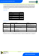
In this mode the IP address and gateway address must be set up manually in the controller.
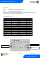
Use the following table as a guide: -
Display
Option
IP1
IP Address byte 1
IP2
IP Address byte 2
IP3
IP Address byte 3
IP4
IP Address byte 4
nL
Network Mask Length (see table below)
GT1
Gateway Address byte 1
GT2
Gateway Address byte 2
GT3
Gateway Address byte 3
GT4
Gateway Address byte 4
ESC
Exit network menu. N.B. this option must be selected to save
any changes made in this menu
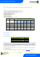
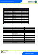
Setting nL
To ease setup, a single network mask length value is used. If the address has been specified with a network mask value in dotted IP
format e.g. 255.255.255.0 then the table below gives the conversion:
Mask
Length
Mask
Length
Mask
Length
255.255.254.0
23
255.254.0.0
15
255.255.255.252
30
255.255.252.0
22
255.252.0.0
14
255.255.255.248
29
255.255.248.0
21
255.248.0.0
13
255.255.255.240
28
255.255.240.0
20
255.240.0.0
12
255.255.255.224
27
255.255.224.0
19
255.224.0.0
11
255.255.255.192
26
255.255.192.0
18
255.192.0.0
10
255.255.255.128
25
255.255.128.0
17
255.128.0.0
09
255.255.255.0
24
255.255.0.0
16
255.0.0.0
08
The network led will start flashing as the controller is logging on to the network; once logged on, the LED stays on.