ML Controller PR0123-TWI ML Twin Compressor Controller Installation & User Guide For Products: - PR0710, PR0711, PR0720, PR0721 Resource Data Management Ltd 80 Johnstone Avenue, Hillington Industrial Estate, Glasgow, Scotland G52 4NZ UK +44(0)141 810 2828 Switchboard support@resourcedm.com Technical Support sales@resourcedm.com Sales Enquiries www.resourcedm.
ML Twin Controller Installation Guide Table of Contents: Introduction ........................................................................................................................................................ 3 Display ................................................................................................................................................................ 3 Relay Modules......................................................................................................
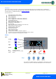
ML Twin Controller Installation Guide Introduction The ML Twin Compressor Controller is a dual stage thermostat with adjustable parameters, incorporating a defrost scheduling timer, lights control, fan control, trim heater control (with energy saving feature by pulsing trim heater) and an alarm handler.
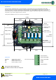
ML Twin Controller Installation Guide Relay Modules The ML controller is supplied in two parts, a panel mount display / control unit and a relay / power supply module in a black ABS enclosure. The two units are interconnected using the 0.75m lead supplied, the control unit derives it’s power from the relay module. All the terminals for power, control relays, networking and temperature probes are contained within the relay module as shown below.
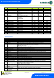
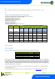
ML Twin Controller Installation Guide Parameter Tables No.
ML Twin Controller Installation Guide No.
ML Twin Controller Installation Guide No.
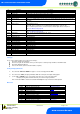
ML Twin Controller Installation Guide Inputs and outputs Selecting this menu option allows the user to view the inputs and outputs. Use the up/down button to select the desired input or output and then press “Enter”. The value will be shown on the display. See View IO Hub/Switch Type Select the desired value for the type of communication module in use.
ML Twin Controller Installation Guide Relay Assignment Relay 1 Relay 2 Relay 3 Relay 4 Relay 5 Compressor Note 1 Fans, Lights, Trims, Solenoid Valve, Alarm, Trim Hub or Compressor Defrost (use the N/O for correct operation) Fans, Lights, Trims, Solenoid Valve, Alarm or Trim Hub Fans, Lights, Trims, Solenoid Valve, Alarm or Trim Hub Note 1: Normally relay 1 operation is from the lower HP switch N/C contact, if the higher HP switch N/O contact is required for normal operation, then rLy1 option in the menu
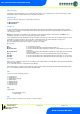
ML Twin Controller Installation Guide ID Sets the controller ID, (normally used in conjunction with the IP-L network mode). Set a number in the range of 1 – 999 RTC Real time clock (This will automatically synchronise on network systems) a. Use the up or down buttons to scroll through the display until the display reads “rtc” b. Press enter. The display will show “t-1”. press enter again c. Scroll hours up or down (0 – 23) press enter d. Use up button to select “t-2”, press enter e.
ML Twin Controller Installation Guide Network Settings IP Communications There are 2 ways the ML controller can be used with an IP Ethernet network: 1. 2. IP-R IP-L Remote IP address given by the Data Manager (DHCP Server) Local IP address and gateway is set up in the controller. IP-R To use the ML controller in IP-R mode, you will require either a PR0016 Mercury IP Module or PR0018 Mercury Hub. When either of these two devices are used, the rotary switches be given a unique setting.
ML Twin Controller Installation Guide SoFt (Software version) Press “Enter” at this display to show the software version. OFSt Probe offsets: - select a channel (1 - 4) and select an offset +/- 20 OC (68 OF) rLY1 Inverts the operation of relay 1 so that the N/O contact can be used. ESC Press enter at this display to quit out of the menu.
ML Twin Controller Installation Guide Single Compressor Operation If a single compressor is configured then the Lag cut-in and Lag Diff parameters are ignored. Compressor 1 will come on when the control temperature reaches Lead Cut-In set point and will go off when the control temperature reaches the Lead Cut-In set point minus the Lead Diff setpoint. In this operational mode the valve icon will be steady on when the compressor is running and off when the compressor is not running.
ML Twin Controller Installation Guide Electric Defrost Cycle Defrost Termination Temperature P-51 Fan Delay Temperature P-49 Control Temperature Comp Relay Termination Time P-45 Drain Down OR Termination Temp P-44 Time P-47 Recovery Time P-48 On Off Normal Operation Fans Relay Defrost Relay Normal Operation On Fan Delay Time P-49 OR Fan Delay Temp P-51 Off On Off Gas Defrost Cycle Defrost Termination Temperature P-51 Fan Delay Temperature P-49 Control Temperature Comp Relay On Off Normal Op
ML Twin Controller Installation Guide From normal operation, when the defrost sequence starts, the fans are switched off (if fans are set to off in defrost, P-50) and the LLV closes. The controller stays in this state until either the termination time (P-45) expires or the termination temperature (p-44) is reached on the defrost termination or air off probe. The controller then enters the drain down period and the fans are switched off.
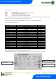
ML Twin Controller Installation Guide View I/O Press “Enter” in the menu at “IO” to view the inputs and outputs. Number I-01 I-02 I-03 I-04 I-05 I-11 I-12 I-14 O-01 O-02 O-03 O-04 O-05 O-06 O-07 O-08 O-09 O-10 O-30 O-31 I/O Control Temp. Probe 1 (Air On) Probe 2 (Air Off) Probe 3 Probe 4 Plant 1 Input Plant 2 Input Hub Trim Level Compressor Relay 2 Defrost Control Relay 4 Relay 5 Lights Trims Fans Compressor 2 Run Time Setpoint Offset Sec Offset Range (dependant on probe type) -60.0 to +60.0 -60.
ML Twin Controller Installation Guide Relays IMPORTANT: Some early versions of Relay modules had relays fitted in position 1 that had a lower N/O contact rating (0.5 HP) Look at the label on the enclosure lid for the correct Relay rating. Relay 1 Compressor Relay Note 1 N/O contact 250 Vac / 16A N/O contact 250 Vac / 2HP N/C contact 250 Vac / 16A N/C contact 250 Vac / 1.