
User guide


Revision 2.2 Page 5 of 14
www.resourcedm.com
Mercury Switch User Guide
Warning
Please Note
The specifications of the product detailed on this
Set-Up Guide may change without notice. RDM
Ltd. shall not be liable for errors or for incidental
or consequential damages, directly and indirectly,
in connection with the furnishing, performance or
misuse of this product or document.
Ensure that all power is
switched off before
installing or maintaining
this product
PR0018-PHI User Guide
The PR0018-PHI hardware version of the Mercury Switch allows for EEV Control on an island by island basis. It also allows for the use of
the energy feature Trim Control which pulses the trim relay of a Mercury case controller based on the actual shop floor humidity therefore
minimising energy usage.
Access to configure the Mercury Switch can be achieved by 2 ways.
Through the front mounted buttons on the display (PR0445)
Across an IP network
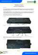
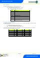
Front Panel Features (PR0445)
4 Character LCD
Down Button
Enter Button
# Button Up Button
Display: The display fits a standard UK single socket pattress.
Enter Button: Button used to enter/confirm values after a change.
Up Button: When in the software menu, the up button is used to scroll up through the menu items.
Down Button: When in the software menu, the down button is used to scroll down through the menu items
# Button: No function
Network LED:
Green LED used to indicate network Status:
Off No network attached
Flashing Attempting to Log on to network
Steady On-line
Amber LED: No function
Alarm LED: Red LED used to indicate an alarm status.
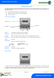
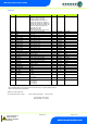
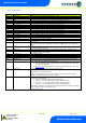
Setup via Display
To enter the software menu for setup mode, hold the Enter and Down buttons together for approximately 3 seconds until the message
“Ent” appears on the display. Release both buttons and now press the Enter button again to enter the software menu. IO is the first item
to be displayed. Scroll up or down to go through the menu items which are highlighted below.