PR0018 PR0018-PHI Mercury Switch User Guide Resource Data Management UK OFFICE Resource Data Management Ltd 80 Johnstone Avenue, Hillington Industrial Estate, Glasgow, Scotland, G52 4NZ, UK +44(0)141 810 2828 sales@resourcedm.com US OFFICE Resource Data Management Inc 100 North Sixth Street, Suite 820C, Minneapolis, MN 55403, USA Tel +1 612 354 2923 Fax +1 612 208 0922 usasales@resourcedm.com www.resourcedm.
Mercury Switch User Guide Table of Contents: THE MERCURY SWITCH ................................................................................................................................... 3 Description ......................................................................................................................................................... 3 Front View ......................................................................................................................................
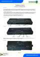
Mercury Switch User Guide The Mercury Switch From Resource Data Management Description The Mercury Switch (PR0018) is a device that allows up to 10 RDM Mercury controllers to be connected to an IP network, without the need for individual IP Futura modules. There are 10 RS232 connections for linking to 10 Mercury controllers. There are 3 standard Ethernet Switch (10/100baseT) connections for other network devices.
Mercury Switch User Guide Connection to Mercury Controllers: Using a standard CAT5 patch lead, connect the serial output of the RDM Controller to one of the RS232 ports of the Mercury Switch. RS232 Lead Lengths RS232 patch lead maximum length must not exceed 15 metres.
Mercury Switch User Guide PR0018-PHI User Guide The PR0018-PHI hardware version of the Mercury Switch allows for EEV Control on an island by island basis. It also allows for the use of the energy feature Trim Control which pulses the trim relay of a Mercury case controller based on the actual shop floor humidity therefore minimising energy usage. Access to configure the Mercury Switch can be achieved by 2 ways.
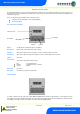
Mercury Switch User Guide Setup Function Menu Display IO PArA ID tyPE nEt SoFt ESC Option Explained in Paragraph View Input and Output States View or change Parameters View or change ID View or change Controller Type View or change the Network Settings View the Software version Escape the menu IO PArA ID type Network Configuration Recommended set-up method Set/View Type a. b. c. From the function menu scroll to select type and press enter The current type is shown.
Mercury Switch User Guide IP-L (Local IP Address) To configure the Mercury Switch for IP-L, set both rotary switches to zero. 1. nEt.
Mercury Switch User Guide Parameters No.
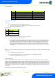
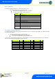
Mercury Switch User Guide Parameters Description Number P-01 P-02 P-03 P-04 P-05 P-11 P-12 P-13 P-14 P-15 P-16 P-17 P-18 P-19 P-20 P-31 P-32 P-33 Parameter Refrigerant Span Offset Glide Pressure Type Evap 1 offset Evap 2 offset Evap 3 offset Evap 4 offset Evap 5 offset Evap 6 offset Evap 7 offset Evap 8 offset Evap 9 offset Evap 10 offset Transducer Fault Delay Alarm Delay HP Alarm P-40 MOP P-41 MOP Diff P-42 P-43 MOP Delay Recovery Count P-50 P-51 P-52 P-53 P-54 Humidity Low Humidity High Trim L
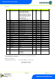
Mercury Switch User Guide Input/Output table Number I-01 I-02 I-03 I-04 I-05 I-06 I-07 I-08 I-09 I-10 I-11 I-12 I-13 I-14 I-15 I-16 O-01 O-02 O-03 O-04 O-05 O-06 O-07 O-08 O-09 O-10 O-11 O-21 O-31 O-32 O-33 O-34 O-35 IO Evap Press Evap 1 Press Evap 2 Press Evap 3 Press Evap 4 Press Evap 5 Press Evap 6 Press Evap 7 Press Evap 8 Press Evap 9 Press Evap 10 Press Humidity Sensor Temp Remote 1 Pressure Remote 1 Pressure Remote 1 Pressure Evap Temp Evap 1 Temp Evap 2 Temp Evap 3 Temp Evap 4 Temp Evap 5 Temp Eva
Mercury Switch User Guide Operation Once the Switch has been correctly setup, it will pass values to each of the controllers connected to ports 1 through 10. In an EEV application the evaporator in temperature probe reading for a case controller can be obtained from the Mercury Switch on which the controller is connected. A suction pressure transducer is connected from the case Island to the 4-20mA input of the Mercury Switch or the pressure read from a remote plant controller.
Mercury Switch User Guide Humidity Control Operation To utilise this feature a Humidity/Temperature Display is required (PR0445). Connect the Humidity/Temperature display to the display port on the Mercury Switch. The control algorithm will use the humidity reading from the display in calculating the percentage at which the trim relays are to be pulsed.
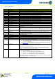
Mercury Switch User Guide Network Alarms The table below shows the text and associated type number that is sent to the system "front end". The type number is normally used to provide different alarm actions. Alarm text Type # (Index) Transducer Fault High Pressure Alarm MOP Alarm Remote Pressure 6 8 3 6 Setup via Webpages The Mercury Switch can be configured by navigating to the Mercury Switch WebPages. This can be achieved by using the Controller Info page in the Data Manager/Data Director.
Mercury Switch User Guide Specification Details Description Power requirements Supply Voltage Range Supply Frequency Typical Supply Current Maximum Supply Current 100 – 240 Vac ±10% 50 – 60 Hz <500mAmps 650mA General Operating Temperature Range Operating Humidity Storage Temperature Range Environmental Size Weight Safety EMC Disposal Origins Ventilation Class 2 Insulation +50C to +500C 80% maximum -200C to +650C Indoor use at altitudes up to 2000m, Pollution Degree II, Installation Category II.