
User guide

Revision 1.0 Page 6 of 29
Warning
Please Note
The specifications of the product detailed on this
Set-Up Guide may change without notice. RDM
Ltd. shall not be liable for errors or for incidental
or consequential damages, directly and indirectly,
in connection with the furnishing, performance or
misuse of this product or document.
Ensure that all power is
switched off before
installing or maintaining
this product
Mercury 3 M & E Installation Guide
www.resourcedm.com
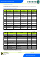
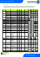
Input and Output Allocation Tables
The following tables indicate; on a controller type basis, the functions of the inputs and outputs. Also shown, are the digital inputs that are
derived by switching in a fixed value resistor across the input.
M-type (Mechanical Expansion Valve or Compressor)
TYPE
Integral Case
Types 1&2
Remote Case
Types 3&4
Coldroom Controller
Types 5&6
Alarm
Action
Plant Input
(Switched
Resistors)
Input 1
Air on Temperature
Air on Temperature
Air on Temperature
Yes
Input 2
Air off Temperature
Air off Temperature
Air off Temperature
Yes
Man Trap alarm
type 5 & 6
Input 3
Evaporator
Temperature
Evaporator Temperature
Evaporator
Temperature
No
Plant fault 1 or
External Defrost
Input
Input 4
Suction Line
Temperature
Suction Line Temperature
Suction Line
Temperature
No
Case Clean Switch
Input 5
Defrost Termination or
Monitor probe (if used)
Defrost Termination or
Monitor probe (if used)
Defrost Termination or
Monitor probe (if used)
Conditional*
Plant fault 2 on
types 1 & 2
Door switch on
types 5 & 6
Input 6
Logging Probe (If fitted)
Logging Probe (If fitted)
Logging Probe (If fitted)
Conditional**
Variable
Input
Not used
N/A
Digital 1
Selectable; Plant 1,
Switch, Defrost, Plant 2
Selectable; Plant 1, Switch,
Defrost
Selectable; Plant 1,
Switch, Defrost, Door,
Man Trap
Conditional
Digital 2
Selectable; Plant 1,
Switch, Defrost, Plant 2
Selectable; Plant 1, Switch,
Defrost
Selectable; Plant 1,
Switch, Defrost, Door,
Man Trap
Conditional
Relay 1
Compressor A
Liquid Line Valve
Liquid Line Valve
N/A
Relay 2
Fans
Fans
Fans
N/A
Relay 3
Lights/Alarm Relay
Lights/Alarm Relay
Lights/Alarm Relay
N/A
Relay 4
Compressor B
Suction Line Valve/Trim
Heater/Alarm Relay/Remote
Relay
Suction Line
Valve/Alarm
Relay/Remote
N/A
Relay 5
Defrost Heater
Defrost Heater (N/O)
Defrost Heater (N/O)
N/A
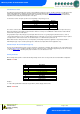
E-type (Electronic Expansion Valve)
TYPE
Remote Case
Types 3&4
Coldroom Controller
Types 5&6
Alarm
Action
Plant Input
(Switched
Resistors)
Input 1
Air on Temperature
Air on Temperature
Yes
Plant fault 1 or
External Defrost
Input 2
Air off Temperature
Air off Temperature
Yes
Case Clean Switch
Input 3
Evaporator Temperature
Evaporator Temperature
Yes
Input 4
Suction Line Temperature
Suction Line Temperature
Yes
Input 5
Defrost Termination or Monitor
probe (if used)
Defrost Termination or Monitor probe (if
used)
Conditional*
Door Switch on
types 5 & 6
Input 6
Logging Probe (If fitted)
Logging Probe (If fitted)
Conditional**
Man Trap on types
5 & 6
Variable
Input mA
Transducer Input (if fitted)
Transducer Input (if fitted)
Yes
Variable
Input V
Transducer Input (if fitted)
Transducer Input (if fitted)
Yes
Digital 1
Selectable; Plant 1, Switch,
Defrost
Selectable; Plant 1, Switch, Defrost, Door,
Man Trap
Conditional
Digital 2
Selectable; Plant 1, Switch,
Defrost
Selectable; Plant 1, Switch, Defrost, Door,
Man Trap
Conditional
Relay 1
Electronic Expansion Valve
Electronic Expansion Valve
N/A
Relay 2
Fans
Fans
N/A
Relay 3
Lights/Alarm Relay
Lights/Alarm Relay
N/A
Relay 4
Suction Line Valve/Trim
Heater/Alarm Relay/Remote Relay
Suction Line Valve/Alarm Relay/Remote
N/A
Relay 5
Defrost Heater (N/O)
Defrost Heater (N/O)
N/A
* Probe will alarms if set to monitor probe in parameters.
** Probe will alarms if log probe type is set to ‘Logging/Alarm’ in parameters