
User guide

Revision 1.0 Page 5 of 29
Warning
Please Note
The specifications of the product detailed on this
Set-Up Guide may change without notice. RDM
Ltd. shall not be liable for errors or for incidental
or consequential damages, directly and indirectly,
in connection with the furnishing, performance or
misuse of this product or document.
Ensure that all power is
switched off before
installing or maintaining
this product
Mercury 3 M & E Installation Guide
www.resourcedm.com
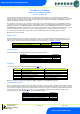
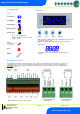
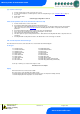
Front Display Features
Mercury Mk3
LED’s: -
Valve (Relay 1)
Fans (Relay 2)
Lights (Relay 3)
Defrost (Relay 5)
On-Line Status
Off No network attached
Flashing Attempting to Log on to network
Steady On-line
Service
(See Parameter
18 for setup)
Alarm
HACCP
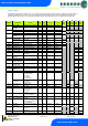
Mercury Mk3 I/O Connections
Input and Output connections are made to the back of the controller, the RS232/ Ethernet communication port is on the side.
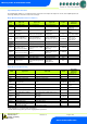
The diagram below shows the connection detail. Inputs and outputs are assigned according to the chosen configuration. See
Input/Output tables for further details on connections. Below also shows you the transducer connections available with the
Mercury Mk 3 E variant.
Keys
Enter Up Down Defrost
Note: Function keys illuminate when pressed, illumination is turned off 20
seconds after the key is used.
Defrost: Press and hold the defrost button to force a manual defrost
Main Display
4 character LED display, used to display temperature and status
messages.
4-20mA Transducer
Connections
0-10V Transducer
Connections
Note: On the Mercury E, relay 1 will be an SSR.
2
1