
User guide


Revision 1.0 Page 26 of 29
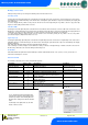
Warning
Please Note
The specifications of the product detailed on this
Set-Up Guide may change without notice. RDM
Ltd. shall not be liable for errors or for incidental
or consequential damages, directly and indirectly,
in connection with the furnishing, performance or
misuse of this product or document.
Ensure that all power is
switched off before
installing or maintaining
this product
Mercury 3 M & E Installation Guide
www.resourcedm.com
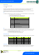
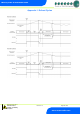
Example of resistor fitted on a probe input.
Switched Resistor Example Wiring
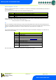
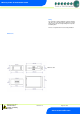
Installation & Dimensions
Panel Cut-out and Clearances
Approx. Weight
177 grams
Safety
EN61010
EMC
EN61326:2013
Ventilation
There is no requirement for forced cooling ventilation
Class 2 Insulation
No protective Earth is required and none should be fitted
Supply Fuse
The host equipment must provide a suitable external over-current protection device such
as: -
Fuse: 2A 240 Vac Anti-surge (T) HRC conforming to IEC 60127
Or MCB
2A, 240 VAC Type C conforming to BS EN 60898
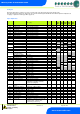
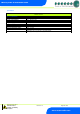
Relay Specification
Relays 1 - 4 Mechanical Type (M) - Exclusive common
Max current
6A Resistive (CosØ = 1)
2A Inductive ( CosØ = 0.4)
Max voltage
250Vac, 30V dc
Relay 1 Solid State Type (E) - Exclusive common
Max current
1.5A
Max voltage
250Vac (ac only, will not switch dc)
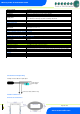
Relay 5 Mechanical Type (M&E) – Exclusive common
Max current
3A (non inductive), COS=0.4 2A (inductive load) 200,000 operations
Max voltage
250Vac
For compliance with the LVD, All relay commons must be at the same potential as the supply voltage
Inputs
Probe Input resistance
3.01K Ohms (for PTC or NTC type probes)
Probe Input type
Selectable. See: Units
Transducer 0-10V
Connect a 0-10v signal
Transducer 4-20mA
4-20mA current loop, uses the 12 Vdc output to feed the pressure transducer See wiring
Digital Inputs
Volt Free
Comms
Serial Variant
RS232 with flow control
Ethernet Variant
IP comms
Connect to remote switch or relay
Probe Ground
Probe Signal