
User guide


Revision 1.0 Page 2 of 29
Warning
Please Note
The specifications of the product detailed on this
Set-Up Guide may change without notice. RDM
Ltd. shall not be liable for errors or for incidental
or consequential damages, directly and indirectly,
in connection with the furnishing, performance or
misuse of this product or document.
Ensure that all power is
switched off before
installing or maintaining
this product
Mercury 3 M & E Installation Guide
www.resourcedm.com
Table of Contents:
THE MERCURY 3 RANGE ................................................................................................................................. 4
Hardware Variants ............................................................................................................................................. 4
Compatible Displays ......................................................................................................................................... 4
Configuration ..................................................................................................................................................... 4
Compatible Network Interfaces ........................................................................................................................ 4
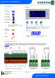
Front Display Features ...................................................................................................................................... 5
Mercury Mk3 .................................................................................................................................................... 5
Mercury Mk3 I/O Connections .......................................................................................................................... 5
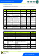
Input and Output Allocation Tables ................................................................................................................. 6
M-type (Mechanical Expansion Valve or Compressor) .................................................................................... 6
E-type (Electronic Expansion Valve) ................................................................................................................ 6
Switched Resistor Values ................................................................................................................................ 7
Transducer Input – Electronic Expansion type only ......................................................................................... 7
Ordering Information ......................................................................................................................................... 7
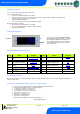
Setting up the controller ................................................................................................................................... 8
Setup through front buttons ............................................................................................................................. 8
Setup Function Menu (Common to all types)................................................................................................... 8
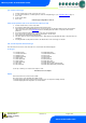
Recommended set-up method ......................................................................................................................... 8
rtc. Real time clock (This will automatically synchronise on network systems) ............................................... 8
type. Set/view controller type ........................................................................................................................... 9
PArA. Set/view parameters (This can be achieved at the network front end) ................................................. 9
Unit. Set/view temperature unit and Probe type .............................................................................................. 9
Display.............................................................................................................................................................. 9
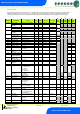
Parameter Tables ............................................................................................................................................. 10
Parameter Descriptions .................................................................................................................................. 13
Load Shedding ................................................................................................................................................. 17
Superheat Options ........................................................................................................................................... 17
EEV Control Using Pressure .......................................................................................................................... 17
Local Analogue Input – mA or V .................................................................................................................... 17
Mercury Switch (PR0018-PHI) ....................................................................................................................... 17
Remote pressure Direct from a Plant Pack Controller ................................................................................... 17
Maximum Operating Pressure (MOP) ............................................................................................................ 17
Relay State and functional operation ............................................................................................................ 18
Relay and screen states during defrost ........................................................................................................ 18
Defrost Type (P-91) ........................................................................................................................................ 18
Defrost Termination ........................................................................................................................................ 18
Fan Delay after Defrost .................................................................................................................................. 18
Network Configuration – RS232 comms ....................................................................................................... 19
RS485 Legacy module ................................................................................................................................... 19
Wireless Mesh Module ................................................................................................................................... 19
IP Futura module ............................................................................................................................................ 20
Mercury Switch ............................................................................................................................................... 20
Network Configuration – IP comms ............................................................................................................... 21
Viewing IO ........................................................................................................................................................ 22
Input / Output Table ....................................................................................................................................... 22
Maximum and Minimum Control Temperature............................................................................................... 23
Display Messages ............................................................................................................................................ 23
Network Alarms ............................................................................................................................................... 23
Modifying controller states ............................................................................................................................. 24
Fans Only “FanS” ........................................................................................................................................... 24
Case Off “CASE” ............................................................................................................................................ 24
Lights Only “Ligt” ............................................................................................................................................ 24
Probe Offset ..................................................................................................................................................... 24
Remote Commands ......................................................................................................................................... 24
Specification .................................................................................................................................................... 25
Switched Resistor Example Wiring ............................................................................................................... 26