
User guide


Revision 1.0 Page 18 of 29
Warning
Please Note
The specifications of the product detailed on this
Set-Up Guide may change without notice. RDM
Ltd. shall not be liable for errors or for incidental
or consequential damages, directly and indirectly,
in connection with the furnishing, performance or
misuse of this product or document.
Ensure that all power is
switched off before
installing or maintaining
this product
Mercury 3 M & E Installation Guide
www.resourcedm.com
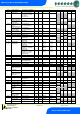
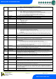
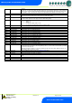
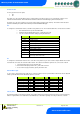
Relay State and functional operation
Relay and screen states during defrost
State:
Pump
Down
Defrost Min
Defrost Max
Drain Down
Fan Delay
Recovery
Screen:
DEF
DEF
DEF
DEF
DEF
REC
Def LED:
On
On
On
Off
Off
Off
RLY 1 LLV
Closed
Closed
Closed
Closed
Open
Open
RLY 4 Suction Line
RLY 4 Trim on in defrost
RLY 4 Trim off in defrost
Off
On
Off
On
On
Off
On
On
Off
On
On
Off
Off
On
Off
Off
On
On
RLY 5 Defrost Relay
Off
On
On
Off
Off
Off
RLY 3 Lights relay
On
On
On
On
On
On
RLY 2 Fans (On in DF)
On
On
On
On
Off
On
RLY 2 Fans (Off in DF)
On
Off
Off
Off
Off
On
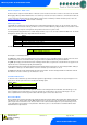
Defrost Type (P-91)
If P-91 is set to gas, compressor 1 is switched on for the duration of the defrost cycle.
Defrost Termination
Defrost termination will be when the temperature parameter “def terminate” has been reached on the “defrost termination” probe. If the
“defrost termination” probe is not fitted, defrost termination will occur when: -
The “coil in” probe reaches the set point (If fans are selected as “off during defrost”)
Or The “air off” probe reaches the set point (If fans are selected as “on during defrost”)
If the “coil in” probe is not fitted, the “air off” probe will be used. If the “air off” probe is faulty termination will occur when the time-out
period has elapsed.
Fan Delay after Defrost
The fans will come back on when: -
The fan delay time has elapsed if the “fan delay mode” is set to time
Or If the fan delay mode is set to “temp”, the fans will come on when the defrost termination probe reaches the fan delay set point,
or on the time parameter, whichever occurs first.
If the “defrost termination” probe is not fitted, the fans will come on when: -
The “coil in” probe reaches the control set point (If fans are selected as “off during defrost”)
Or The “air off” probe reaches the control set point (If fans are selected as “on during defrost”)
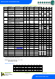
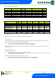
Relay 1-3 State
Function State
Wired
contact
Relay 4-5 State
Function State
Wired
contact
Relay 1 off
Valve / Comp. A on
N/C
Relay 4 off
Suction or Trims off
N/O
Relay 1 on
Valve / Comp. A off
N/C
Relay 4 on
Suction or Trims on
N/O
Relay 2 off
Fans on
N/C
Relay 4 off
Alarm Relay = Alarm
N/C
Relay 2 on
Fans off
N/C
Relay 4 on
Alarm Relay = OK
N/C
Relay 3 off
Lights on
N/C
Relay 4 off
Compressor B off
N/O
Relay 3 on
Lights off
N/C
Relay 4 on
Compressor B on
N/O
Relay 3 off
Alarm Relay = Alarm
N/C
Relay 5 off
Defrost control off
N/O
Relay 3 on
Alarm Relay = OK
N/C
Relay 5 on
Defrost control on
N/O