
User guide


Revision 1.0 Page 14 of 29
Warning
Please Note
The specifications of the product detailed on this
Set-Up Guide may change without notice. RDM
Ltd. shall not be liable for errors or for incidental
or consequential damages, directly and indirectly,
in connection with the furnishing, performance or
misuse of this product or document.
Ensure that all power is
switched off before
installing or maintaining
this product
Mercury 3 M & E Installation Guide
www.resourcedm.com
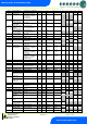
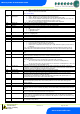
energy feature Trim Control then the Data Manager feature will override this parameter setting. Please
refer to the Data Manager user document for further details. Note the trims are turned off when an over
temperature alarm occurs.
P-85
Key-switch Mode
Allows the keys switch to be: -
Single turn for case off (Case off mode)
Single turn for Fans only (Fans Mode)
Single turn for case off, double turn for fans only (Toggle mode)
P-87
Control Probe type
Switches between using the air-on probe and the Logging probe. Note the control and display
temperature will still be a derivative of the weighted
Average of the control probe + Air-off probe
P-90
Resistor Case Off
Turns on/off the switched resistor case off function
P-92
Fans temperature
mode
Allows the user to set the fans to turn off when: -
A pre-determined temperature is reached (P93)
When an over-temperature alarm is present
When either P93 is reached or an OT alarm is present
P-93
Fans Off Temperature
Temperature for the above (P92) operation. Note the defrost termination probe is the source of the
temperature reading used in this feature. If the defrost termination probe isn’t fitted then a similar process
to P-44 is used.
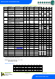
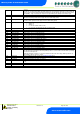
P-83
Fan Control
This feature allows for coldroom fans to be stopped when the coldroom is down to temperature thus
saving energy. This feature is present in both the M and E software.
Run – fans operate as per the normal control strategy.
Pulse – When the LLV closes the fans will stop when the Fan Pulse On parameter (P-78) time
expires. The fans then remain off for the Fan Pulse Off time (P-79). When the parameter Fan
Pulse Off time expires the fans come back on for the Fan Pulse on time. The cycle then
repeats. The fans resume normal operation if the LLV operates. The fans pulse on/off to ensure
the circulation of air within the coldroom.
Off – When the LLV closes the fans stay on for the Fan Pulse On (P-78) time before going off
until the LLV next operates.
Placement of the temperature control probes is important when using this feature
P-78
Fan Pulse On
The duration of the fans are pulsed on in Fan Control.
P-79
Fan Pulse Off
The duration of the fans are pulsed off in Fan Control.
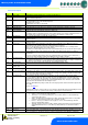
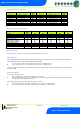
P-15
Probe 5 Select
This input can be used as a defrost termination probe (default) or as a monitor probe with an OT alarm
level (P-28)
P-16
Relay 3 mode
This changes the function of relay 3 from Lights (default) to an alarm relay. The alarm relay is energised
for no alarm. Use the NC and Common for “Loop make” on alarm or use the NO and Common for “Loop
break” on alarm.
P-17
Evap Select
This allows the control algorithm to use a remote temperature input in place of the evaporator in value. In
the event of no remote value being received, the control algorithm will revert to using the evaporator in
probe value until the remote value is restored.
Please see: EEV Control Using Pressure.
P-97
Control Fail Valve
Value
This value is used in the event of a control probe fail; In the EEV control algorithm the valve will remain at
this opening until the probe fault has been cleared. Please note the incorrect setting of this value may
result in flood back causing damage to the pack compressors. Do not adjust this parameter if you are
unsure of the consequences. In M software this is the value to which the LLV/compressor relay will be
pulsed open/closed. For example if set to 2 minutes then the LLV will be open for 2 minutes and then
closed for two minutes. This process will continue until the control probe fail has been rectified.
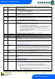
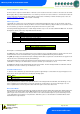
P-29
Probe 1 or Probe 3
Resistor
Selects whether the switched resistor invokes either a Plant fault or an External Defrost. If E software then
probe input 1 is used. If M software then probe input 3 is used.
P-18
Service Interval Time
(Run Hours)
Time (in 1000 x hours) before the service icon (Spanner icon) comes on. The Run Hours timer increments
based on the number of hours the controller has been powered up and running. Reset the spanner icon to
off by changing this parameter to 0 and then back to the desired service interval. This process also resets
the Run Hours value to 0. To view the current Run Time value refer to the I/O list.
P-19
Switch Resistors
Enables switched resistors to be used for Plant Faults, External Defrosts, Case Clean, Man Trap, Door
Switch
See : Switched Resistor Values
P-77
Man Stop LLV/Fans
When man trap input is activated the LLV closes and Fans are stopped. Normal operation resumes when
the mantrap input is deactivated.
P-98
Lights Case Off
Used to place the controller into Case Off when its lighting timer is in the off state. When the lighting timer
is in the on state the controller follows its normal control operation. This feature is disabled if the set point
(P-01) is below 6
o
C. Please note that when the controller is in case off all alarms are inhibited and all
outputs are turned off. Therefore care must be taken when enabling this parameter.
Off – Feature is not used and only the controller lights relay follows the lighting timer status.
On - Feature is in use and controller will be in Case Off whenever the lights timer is in the off
state.
Unused – This selection has no effect and should not be used. Please select from either Off or
On. This feature operates in either Local, using controller RTC, or Remote, using Data Manager
GP timer channel, lighting applications.
P-99
Load Shedding
Off – Feature is not used