
User guide


Revision 1.0 Page 13 of 29
Warning
Please Note
The specifications of the product detailed on this
Set-Up Guide may change without notice. RDM
Ltd. shall not be liable for errors or for incidental
or consequential damages, directly and indirectly,
in connection with the furnishing, performance or
misuse of this product or document.
Ensure that all power is
switched off before
installing or maintaining
this product
Mercury 3 M & E Installation Guide
www.resourcedm.com
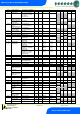
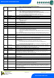
Parameter Descriptions
Number
Parameter
Description
P-01
Cut-in Temp
Temperature at which the EEV/ LLV or compressor will switch on.
P-02
Diff
Differential temperature below the cut-in temperature. The EEV/ LLV or lead compressor switches off
when below this temperature.
P-03
Control Weight
Percentage of the Air-On temperature that is used to calculate the control temp. The remaining
percentage will be used on the Air-Off temperature.
Example, P-03 set to 30%
Control temp = 30% Air-on + 70% Air-off
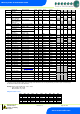
P-04
Display Weight
As above only applied to the display temperature
P-05
Lag Comp Delay
Delay before the second compressor is switched on if the temperature is still above set-point.
P-06
Anti SC Time
Allows the user to set the compressor for a given number of starts/hour
P-07
Lag Cut Out Diff
Diff below the Cut-In Temp the lag compressor switches off.
Single Compressor Operation
To disable compressor B operation and use only a single compressor for control set parameter P-07 to 0.
This will allow the controller work with just one compressor (A) and ignore compressor B.
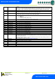
P-08
Superheat Ref
The controller will attempt to maintain this superheat value
P-09
Response on
Allows the user to speed up the EEV on time. With 30 providing the quickest response and 1 providing the
slowest response.
P-10
Response off
Allows the user to speed up the EEV off time. With 30 providing the quickest response and 1 providing the
slowest response.
P-11
Control Type
Allows the user to select either EEV control, EET control or EEV/EET control. Note the Evaporator
Temperature probe should be fitted to the coldest point in the evaporator.
EEV uses the superheat as its main reference with the cabinet temperature as a secondary control.
EET use the cabinet temperature as its main reference.
EEV/EET uses cabinet temperature as the main control until the SH gets close to the SH reference point,
then it switches to EEV control, it switches back to EET control when the SH reference is satisfied.
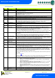
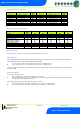
P-51
EEV Minimum Opening
Sets the minimum valve opening level, during normal operation the valve will not go below this level.
(Default 10%)
IF used in conjunction with a Mercury Pressure Hub PR0018-PHI, remote pressure from Plant Pack or
local pressure from a daughter card, then the Minimum value should be set at 0%
P-52
Superheat Problem
Sets the point at which the algorithm will go to the “EEV Problem” state due to the superheat temperature.
For example if this parameter is set to 0 Degrees and the Superheat value falls to 0 degrees or below, for
the duration of P-54, then the controller will enter the superheat problem state.
P-53
Superheat EEV
Problem Opening
Sets the valve open position when entering the “Superheat EEV Problem” state.
P-54
Superheat EEV
Problem Time
Sets the time the algorithm stays in the “Superheat EEV Problem” state.
P-56
EEV Start Opening
Sets the valve opening % which is used immediately after the device is powered on.
P-55
Average Valve Opening
Normally the valve during recovery will open to the last average position. This setting allows for that value
to be reduced by said percentage. For example if the average valve opening is calculated as 80% and P-
55 is set to 50% then the valve will open at 40%.
P-57
EEV Divide value
This parameter only takes effect when the controller is used in conjunction with a Mercury Switch
pressure application. When the Mercury Switch generates the MOP alarm the controller reduces the
maximum valve opening to this percentage. For example if this parameter is set to 50% and the MOP
alarm is generated then the maximum valve opening will be limited to 50%. Therefore as the controller
pulses the valve the maximum the valve will open is 50%.
Note P-51 EEV Minimum opening overrides the valve output operation and the valve will not pulse below
this setting.
Please see MOP note.
Please note parameters P-51 through to P-57 should not be altered without first understanding the effects
they may have on the case operation. If incorrectly set they may have undesired affects.
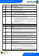
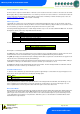
P-12
Relay 4 Mode
Relay 4 can be a Suction, Trim Heater, Alarm, Remote or Trim Hub relay.
Suction – set for Suction Line Valve operation.
Trim Heater – set as trim relay which pulses in accordance with P-14 or the Data Manager
energy feature trim control.
Alarm – The alarm relay is energised for no alarm. Use the NC and Common for “Loop make”
on alarm or use the NO and Common for “Loop break” on alarm.
Remote – The relay is available for remote purposes such as the Data Manager GP timer
channel or Data Builder software.
Trim Hub – Relay is pulsed in accordance with the Trim Control feature present in the Mercury
Switch (PR0018-PHI). Please see the Mercury switch (PR0018) user document for further
details.
P-13
Trim in Defrost
Allows the trims to be off or on during a defrost.
P-14
Trim Level
Sets a percentage level, of a 5-minute period, to pulse the trim heater relay off/on. Example: - P-14 set to
50% = 2.5 minutes on, 2.5 minutes off. If the controller is networked to a Data Manager operating the