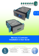
PR0740 - CAS Mercury 3 Controller Installation & User Guide Resource Data Management UK OFFICE Resource Data Management Ltd. 80 Johnstone Avenue, Hillington Industrial Estate, Glasgow, Scotland, G52 4NZ, UK +44(0)141 810 2828 sales@resourcedm.com US OFFICE Resource Data Management USA Inc. 100 North 6th Street, Suite 630B, Minneapolis, MN 55403, USA +1 612 354 3923 +1 612 208 0922 usasales@resourcedm.
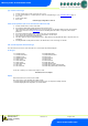
Mercury 3 M & E Installation Guide Table of Contents: THE MERCURY 3 RANGE ................................................................................................................................. 4 Hardware Variants ............................................................................................................................................. 4 Compatible Displays ...........................................................................................................................
Mercury 3 M & E Installation Guide Installation & Dimensions ............................................................................................................................... 26 Panel Cut-out and Clearances ....................................................................................................................... 26 Fixing ..............................................................................................................................................................
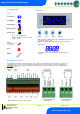
Mercury 3 M & E Installation Guide The Mercury 3 Range From Resource Data Management For Version 1.0M & 1.0E The Mercury Mk3 controller is primarily intended for use in refrigeration display cabinets or coldroom applications. It will switch the evaporator valve (LLV or EEV) based on the value of its temperature or pressure input. It has outputs to control lights, fans, suction valve, trim heaters and defrost control.
Mercury 3 M & E Installation Guide Front Display Features Mercury Mk3 LED’s: Valve (Relay 1) Fans (Relay 2) Lights (Relay 3) Defrost (Relay 5) Keys On-Line Status Off No network attached Flashing Attempting to Log on to network Steady On-line Service (See Parameter 18 for setup) Enter Up Down Defrost Note: Function keys illuminate when pressed, illumination is turned off 20 seconds after the key is used.
Mercury 3 M & E Installation Guide Input and Output Allocation Tables The following tables indicate; on a controller type basis, the functions of the inputs and outputs. Also shown, are the digital inputs that are derived by switching in a fixed value resistor across the input.
Mercury 3 M & E Installation Guide Switched Resistor Values The switched resistor functionality can be turned on and off within the parameter section (P-19). When switched on, it adds the benefit of adding further digital inputs for switches using fixed resistors. For wiring please see the ‘Switched Resistor Wiring’ section.
Mercury 3 M & E Installation Guide Setting up the controller Access to the controller can be achieved by several ways; Serial Communications Variant Through the front mounted buttons of the display Direct access by PC into the serial comms port. This requires a software package available on the RDM website. Through legacy front end panels on 485 networks. Through the RDM Data Manager. Across an IP network (Current controller IP address required).
Mercury 3 M & E Installation Guide type. Set/view controller type a. b. c. d. e. From the function menu scroll to select ‘type’, press enter Use the up/ down buttons to scroll through case/ coldroom configuration types. (see configuration table on page 4) Press enter. Scroll to select “ESC” Press enter Controller type configuration is now set PArA. Set/view parameters (This can be achieved at the network front end) a. b. c. d. e. f. g. h.
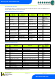
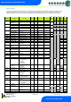
Mercury 3 M & E Installation Guide Parameter Tables Not all parameters apply to all controller types. For example P-08 is the Superheat reference which only applies to the EEV variant of controllers (available types on the E are 3, 4, 5 & 6). This parameter will not appear if the controller is a Mechanical variant. In the following table, the type columns on the right hand side will be greyed out if that parameter does not apply to that controller type.
Mercury 3 M & E Installation Guide P-15 P-16 P-17 Probe 5 Select Relay 3 Mode Evap Select P-97 Control Fail On/Off (Mechanical Valve) Control Fail Valve Level (EEV) P-29 0 = Defrost, 1 = Monitor 0 = Lights, 1 = Alarm 0 = Local 1 = Rem1, 2 = Rem2, 3 = Rem3, 4 = Trans V, 5= Trans mA 00:00 to 10:00 0 to 100% 1 1 1 01:00 mm:ss 0.
Mercury 3 M & E Installation Guide 00:00 to 24:00 00:15 mm:ss 01:30 00:30 00:00 to 99:00 00:00 to 99:00 0 = Time 1 = Temp 00:00 to 99:00 01:00 01:00 1 01:00 mm:ss mm:ss 30:00 00:00 0 00:00 mm:ss 30:00 00:00 0 00:00 00:00 to 99:00 01:00 mm:ss 03:00 03:00 -42 to 30 (-43.6 to 86) 0 (Off), 1 (On) 0 (Off), 1 (On) 0.1 Deg -20 (-4) On Off 0.0 (32) On Off 0 = Elec. 1 = Elce/CIn 0 = Elec. 1 = Gas.
Mercury 3 M & E Installation Guide Parameter Descriptions Number P-01 P-02 Parameter Cut-in Temp Diff P-03 Control Weight P-04 P-05 P-06 P-07 Display Weight Lag Comp Delay Anti SC Time Lag Cut Out Diff P-08 P-09 Superheat Ref Response on P-10 Response off P-11 Control Type P-51 EEV Minimum Opening P-52 Superheat Problem P-53 Superheat EEV Problem Opening Superheat EEV Problem Time EEV Start Opening P-54 P-56 P-55 P-57 Description Temperature at which the EEV/ LLV or compressor will swit
Mercury 3 M & E Installation Guide P-85 Key-switch Mode P-87 Control Probe type P-90 P-92 Resistor Case Off Fans temperature mode P-93 Fans Off Temperature P-83 Fan Control P-78 P-79 P-15 Fan Pulse On Fan Pulse Off Probe 5 Select P-16 Relay 3 mode P-17 Evap Select P-97 Control Fail Valve Value P-29 Probe 1 or Probe 3 Resistor Service Interval Time (Run Hours) P-18 P-19 Switch Resistors P-77 Man Stop LLV/Fans P-98 Lights Case Off P-99 Load Shedding energy feature Trim Control th
Mercury 3 M & E Installation Guide P-100 / P-101 Digital Input 1 / Digital Input 2 P-20 P-21 P-22 P-23 Alarm Delay UT Alarm OT Alarm Log Probe Type P-24 Slug Log Probe P-25 P-26 P-27 P-28 P-40 Log Alarm Delay Log UT Alarm Log OT Alarm Monitor OT Alarm Defrost Mode P-41 P-42 Defrost Start Defrosts per Day P-43 No Defrost Time P-44 Def Terminate P-45 Def Min Time P-46 P-47 P-48 Def Max Time Drain Down Recovery Time P-89 P-86 Pump Down Time Fan Delay mode P-49 P-88 P-50 Fan Delay Fan
Mercury 3 M & E Installation Guide P-80 P-81 Door alarm delay Door Closes Valve P-82 Door Stops Fan P-60 Lights Mode P-61 P-62 P-63 P-64 P-65 P-66 P-67 P-68 P-69 P-70 P-71 P-72 P-73 P-74 P-30 Sun Lights On Sun Lights Off Mon Lights On Mon Lights Off Tue Lights On Tue Lights Off Wed Lights On Wed Lights Off Thu Lights On Thu Lights Off Fri Lights On Fri Lights Off Sat Lights On Sat Lights Off Broadcast ID P-31 P-32 P-33 P-34 Refrigerant Pressure Units Evap Offset Glide P-35 P-36 dFLt Trans Span T
Mercury 3 M & E Installation Guide Load Shedding Used on CO2 sites for load shedding on CO2 Compressor Faults or CO2 Vessel High Pressure Alarms. Cases can be put into a “CO2 Case Off” mode which will open the LLV/EEV and stop the fans to reduce the load on the pack or to reduce the CO2 vessel pressure. See: RDM CO2 load shedding user guide.
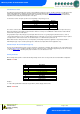
Mercury 3 M & E Installation Guide Relay State and functional operation Relay 1-3 State Function State Relay 1 off Relay 1 on Relay 2 off Relay 2 on Relay 3 off Relay 3 on Relay 3 off Relay 3 on Valve / Comp. A on Valve / Comp.
Mercury 3 M & E Installation Guide Network Configuration – RS232 comms The final section to setup is the network address. In all instances, this must be done before the controller is connected to the site network. When logging a Mercury 3 with an RS232 interface onto a network you must first connect the controller to a communications module, this is either a 485 Legacy, IP Futura, Mercury Switch or Wireless Mesh Interface.
Mercury 3 M & E Installation Guide IP Futura module In an IP system there are two options; IP-L IP-r IP-L allows you to fix a static IP address into the controller, which you would use when you are connecting the controllers onto a customer’s local area network. This would allow the customer to view each controller using a generic Internet browser. IP-r allows you to give each controller on the system a unique number (using the rotary switches).
Mercury 3 M & E Installation Guide Network Configuration – IP comms Mercury 3 controllers with the IP interface as standard does not require any communications module and will already communicate on the IP network protocol.
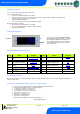
Mercury 3 M & E Installation Guide Viewing IO Apart from setting up the controller, you can also view the status of the inputs and outputs and controller states. From the function menu, select “I/O”, press enter. You can now scroll through the IO table as set out below. Inputs and outputs that do not apply to a particular controller type will be greyed out.
Mercury 3 M & E Installation Guide S-02 7 (OT Alarm), 8 (UT Alarm), 9 (Fans Only), 10 (Lights Only), 11 (Case Off),12 (Pump Down), 13 (Defrost Hold), 14 (Load Shed) 0 (Off), 1 (Start), 2 (Run), 3 (Problem), 4 (Fail), 5 (Shed) Valve State * Range is dependent on probe type Maximum and Minimum Control Temperature Type M only (Not supported in type E).
Mercury 3 M & E Installation Guide Modifying controller states During normal operation you can change the following states from the function menu Fans Only “FanS” Selecting the Fans Only option will put the controller into the Fans Only state if the current state is not Fans Only. If the current state is Fans Only then the controller will change to the Normal state. Selecting this option will exit the setup menu automatically.
Mercury 3 M & E Installation Guide Specification Mercury Mk3 Controller PR0740 xxx CAS Power requirements Supply Voltage Range Supply Frequency Typical supply current General Operating temperature range Storage temperature range Environmental Size 100 – 240 Vac ±10% 50 – 60 Hz <1 Amp +50C to +500C -200C to +650C Indoor use at altitudes up to 2000m, pollution degree 2, installation category II. Voltage fluctuations not to exceed ±10% of nominal voltage.
Mercury 3 M & E Installation Guide Approx.
Mercury 3 M & E Installation Guide Fixing The controller is fixed by sliding the 2 plastic retaining clips up to rear of the panel. These clips have a ratchet action and can be removed by holding in the clip sides and sliding back. There is no requirement for forced cooling ventilation Dimensions Cleaning Do not wet the controller when cleaning. Clean the front by wiping with slightly damped lint free cloth.
Mercury 3 M & E Installation Guide Appendix 1: Defrost Cycles Warning Ensure that all power is switched off before installing or maintaining this product Revision 1.0 Page 28 of 29 www.resourcedm.
Mercury 3 M & E Installation Guide Appendix 2: Trim Heater Control via Mercury/Intuitive Range Energy savings via the RDM’s range of case controllers can be achieved in a number of ways. One of which is pulsing the trim heater relay off for a given period of time. One way to pulse the trim heater is by configuring P-14. For greater energy savings the Data Manager energy feature trim control or the Mercury Switch trim control feature can be used.