
User guide


Revision 7.1b Page 9 of 31
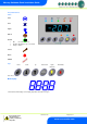
Mercury Coldroom Panel Installation Guide
www.resourcedm.com
Warning
Please Note
The specifications of the product detailed on this
Set-Up Guide may change without notice. RDM
Ltd. shall not be liable for errors or for incidental
or consequential damages, directly and indirectly,
in connection with the furnishing, performance or
misuse of this product or document.
Ensure that all power is
switched off before
installing or maintaining
this product
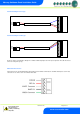
Input/Output Allocation Tables
The following tables indicate; on a controller type basis, the functions of the inputs and outputs. Also shown are the digital inputs that are
derived by switching in a fixed value resistor across the input
Inputs and Outputs
Coldroom Panel
Models: All
Alarm Action
Comments
Earth
Bus-bar
N/A
This unit must be Earthed
L1
Incoming Live Feed
N/A
Connection on the isolator
L2
Not Used
N/A
L3
Incoming Neutral Feed
N/A
Connection on the isolator
L
Incoming Live Feed
N/A
On the PCB (Non-isolator version)
N
Incoming Neutral Feed
N/A
On the PCB (Non-isolator version)
Input 1
Air on Temperature
Yes
Grey probe Connector
Input 2
Air off Temperature
Yes
Grey probe Connector
Input 3
Evaporator Temperature
No
Grey probe Connector
Input 4
Suction Line Temperature
No
Grey probe Connector
Input 5
Defrost Termination (if used)
No
Grey probe Connector
Input 6
Logging Probe (If fitted)
Conditional
Grey probe Connector
Door Switch
Door Switch
Yes
Uses Ground Return
Entrapment Switch
Entrapment Switch
Yes
Uses Ground Return
Compressor/LLV
N/O and N/C (N/O only on EEV)
N/A
See Specification for further details
Defrost
N/O and N/C
N/A
See Specification for further details
Fans
N/C
N/A
See Specification for further details
Lights
N/O and N/C
N/A
See Specification for further details
Out 1
Always Live (heater mats)
N/A
See Specification for further details
Out 2
Always Live (PRV)
N/A
See Specification for further details
Alarm
N/O, N/C & Common (Volt-free)
N/A
See Specification for further details
Note: -
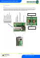
For PT1000 probes, jumpers; LK1 & LK2, are in the outer positions for the additional switched resistor functions to operate.
For NTC probes, jumpers; LK1 & LK2, are in the inner positions for the additional switched resistor functions to operate.
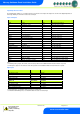
Digital Inputs
Models: M
Alarm Action
Plant input
Fixed input on PCB
Yes
Man trap
Fixed input on PCB
Yes
Door Switch
Evaporator Probe
Conditional
Plant fault 1/External defrost input*
Suction Line Probe
No
Case Clean*
Models: E
Alarm Action
Plant input
Fixed input on PCB
Yes
Man trap
Fixed input on PCB
Yes
Door Switch
Air on Temperature Probe
Conditional
Plant Fault 1/External defrost input*
Air off Temperature Probe
No
Case Clean*
* For PT1000 probes, use 820 Ohm switched resistors to activate input.
For NTC2K and NTC2K25 probes, use 590 Ohm switched resistors to activate input.