
User guide

Revision 7.1b Page 29 of 31
Mercury Coldroom Panel Installation Guide
www.resourcedm.com
Warning
Please Note
The specifications of the product detailed on this
Set-Up Guide may change without notice. RDM
Ltd. shall not be liable for errors or for incidental
or consequential damages, directly and indirectly,
in connection with the furnishing, performance or
misuse of this product or document.
Ensure that all power is
switched off before
installing or maintaining
this product
Appendix 1
For later hardware revisions of Coldroom panels the Compressor/LLV and Defrost MCB/Fuse can be interchanged to allow the higher
rated MCB/Fuse, 20A, to be used on the Compressor/LLV relay output and the lower rated MCB/Fuse, 10A, to be used on the Defrost
relay output. By default the Coldroom panel ships with the 20A MCB/Fuse fitted to the Defrost relay and the 10A MCB/Fuse fitted to the
Compressor/LLV.
Changing the configuration of this part must be carried out by competent personnel. RDM will not be held responsible for any damage incurred to the
equipment through mishandling or faulty installation when carrying out this work. If unsure do not carry out this procedure and contact RDM Technical
Support for further assistance.
Instructions – MCB Variants
1) Before working on this equipment, ensure that the device is fully isolated from any supply voltage, including connections to all relays and other
I/O connectors.
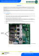
2) Open the Coldroom front panel by unscrewing the screw fixings at the top right and bottom right of the panel door. If an Isolator
switch is fitted to the Coldroom panel then this must be in the off position before the door will open.
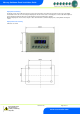
3) Locate the MCB’s. Note a fixing plate is attached over the MCB’s.
4) On the fixing plate a label is affixed indentifying each output and the current rating in Amps for the associated MCB for the
default configuration. Note the ratings of the MCB’s are marked on the side of the MCB and they should be checked to ensure
the current MCB rating and position matches that indicated by the label.
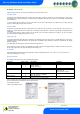
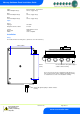
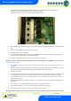
5) To swap the higher rated Defrost MCB over with the Compressor/LLV MCB firstly unscrew the plastic washer for all four
MCB’s.
6) Now remove the two screws at the top and bottom of the fixing plate.
Plastic Mounting Nut
Screw Fixing
Points For
Fixing Plate