
User guide

Revision 7.1b Page 23 of 31
Mercury Coldroom Panel Installation Guide
www.resourcedm.com
Warning
Please Note
The specifications of the product detailed on this
Set-Up Guide may change without notice. RDM
Ltd. shall not be liable for errors or for incidental
or consequential damages, directly and indirectly,
in connection with the furnishing, performance or
misuse of this product or document.
Ensure that all power is
switched off before
installing or maintaining
this product
Switched Resistor Values
For PT1000 probes use 820 Ohm switched resistors. For NTC2K and NTC2K25 probes use a 590 Ohm switched resistor. For NTC10K
probes use 2k7 Ohm switched resistors. For NTC10K(2) probes use 2k2 Ohm switched resistors. The resistors used must have a
tolerance of 1% or better and the resistor must have a power rating of 0.25W. For improved accuracy whilst using switched resistors
RDM recommend resistors with 0.1% accuracy are used. Note the switched resistor features will not function when using 470R or 700R
probes. When a resistor is switched across the appropriate input it signals to the Mercury to enable the switched resistor function
described for that input whilst still recording the probe temperature on the input.
Temperature range for all probe types is -49
o
C to +60
o
C
for probe inputs which do not have a secondary function (switched resistors).
Inputs which have a secondary function are restricted to -42
o
C to +60
o
C.
Note: switched resistors will operate in LT (Low Temperature) and HT (High Temperature) applications using PT1000, NTC2K or
NTC2K25 probe types only. For all other probe types the switched resistor inputs will work in HT applications only.
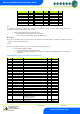
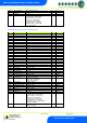
Alarm Messages
The following alarms and messages can appear on the Mercury display.
Display Message
System status
Ft
Control Fault
Prb1
Probe 1 Fault
Prb2
Probe 2 Fault
Prb3
Probe 3 Fault
Prb4
Probe 4 Fault
Prb5
Probe 5 Fault
Prb6
Probe 6 Fault
Pd
Control State in Recovery
dEF
Control Sate in Defrost
AL
Control State in Alarm
FAnS ONLy
Controller in Fans Only
Ligt ONLy
Controller in Lights Only
CASE OFF
Controller in Case Off
Ot
Over Temperature Alarm
Ut
Under Temperature Alarm
door
Door Open Alarm
Man TrAP
Person Trapped Alarm
PLnt
Plant Fault
LgOt
Log Probe Over Temperature
LgUt
Log Probe Under Temperature
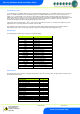
Network Alarms
The table below shows the text and associated type number that is sent to the system "front end". The type number is normally used to
provide different alarm actions.
Alarm text
Type # (index)
Missed defrost
15
Plant Fault 1
3
Case over temperature
4
Case under temperature
5
Probe 1 Faulty
6
Probe 2 Faulty
6
Probe 3 Faulty
6
Probe 4 Faulty
6
Probe 5 Faulty
6
Probe 6 Faulty
6
Door Left Open
2
Product over temperature
8
Product under temperature
9
Person Trapped
1