
User guide


Revision 7.1b Page 2 of 31
Mercury Coldroom Panel Installation Guide
www.resourcedm.com
Warning
Please Note
The specifications of the product detailed on this
Set-Up Guide may change without notice. RDM
Ltd. shall not be liable for errors or for incidental
or consequential damages, directly and indirectly,
in connection with the furnishing, performance or
misuse of this product or document.
Ensure that all power is
switched off before
installing or maintaining
this product
Table of Contents:
THE MERCURY RANGE ....................................................................................................................................4
Networks .............................................................................................................................................................4
Configuration .....................................................................................................................................................4
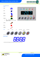
Front Panel Features .........................................................................................................................................5
Connections .......................................................................................................................................................6
Mains Input and Outputs ..................................................................................................................................6
Probe and Alarm inputs....................................................................................................................................7
Internal Cable Diagram for LLV type ................................................................................................................8
Internal Cable Diagram for EEV type ...............................................................................................................8
RS485 Network Connection. ............................................................................................................................8
Input/Output Allocation Tables .........................................................................................................................9
Inputs and Outputs ...........................................................................................................................................9
Digital Inputs ......................................................................................................................................................9
Setting up the Panel ....................................................................................................................................... 10
Setup through the keypad ............................................................................................................................. 10
Setup Function Menu .................................................................................................................................... 10
Pin Menu Access .......................................................................................................................................... 10
Recommended set-up method ...................................................................................................................... 11
rtc. Real time clock (This will automatically synchronise on network systems) ............................................ 11
type. Set/view controller type ........................................................................................................................ 11
Unit. Set/view temperature unit and Probe type ........................................................................................... 11
Probe Types .................................................................................................................................................. 11
Display........................................................................................................................................................... 11
PArA. Set/view parameters (This can be achieved at the network front end) .............................................. 12
Parameter Table for Compressor/LLV type: ................................................................................................ 12
Parameter table for EEV Type ....................................................................................................................... 13
Parameters Description ................................................................................................................................. 15
Load Shedding ................................................................................................................................................ 18
EEV Control Using Pressure ......................................................................................................................... 18
Mercury Switch (PR0018-PHI) ...................................................................................................................... 18
Remote pressure Direct from a Plant Pack Controller .................................................................................. 18
Maximum Operating Pressure ...................................................................................................................... 18
Network Configuration ................................................................................................................................... 19
485 Legacy module ....................................................................................................................................... 19
IP Futura module ........................................................................................................................................... 20
Viewing ............................................................................................................................................................ 21
Input/Output table for Coldroom Panel with Compressor/LLV option ........................................................... 21
Input/Output table for Coldroom Panel with EEV option ............................................................................... 22
Switched Resistor Values ............................................................................................................................. 23
Alarm Messages ............................................................................................................................................. 23
Network Alarms .............................................................................................................................................. 23
Fans Only “FAnS” ......................................................................................................................................... 24
Case Off “CASE” ........................................................................................................................................... 24
Lights Only “Ligt” ........................................................................................................................................... 24
Probe Offset .................................................................................................................................................. 24
Remote Commands: ....................................................................................................................................... 24
Installation ....................................................................................................................................................... 26
Fixing ............................................................................................................................................................. 26
Display Remote Mounting ............................................................................................................................. 27
Display dimensions and fixing ....................................................................................................................... 27
Part Numbers .................................................................................................................................................. 28
Disclaimer: ...................................................................................................................................................... 28
APPENDIX 1 .................................................................................................................................................... 29
Instructions – MCB Variants ......................................................................................................................... 29
Instructions – Fuse Variants ......................................................................................................................... 30