
User guide


Revision 7.1b Page 19 of 31
Mercury Coldroom Panel Installation Guide
www.resourcedm.com
Warning
Please Note
The specifications of the product detailed on this
Set-Up Guide may change without notice. RDM
Ltd. shall not be liable for errors or for incidental
or consequential damages, directly and indirectly,
in connection with the furnishing, performance or
misuse of this product or document.
Ensure that all power is
switched off before
installing or maintaining
this product
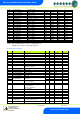
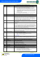
Relay State and functional operation
Relay State:
Function State
Wired contact
Comments
Compressor/LLV Relay off
Valve on
N/C
Compressor/LLV Relay on
Valve off
N/C
Fans Relay off
Fans on
N/C
Fans Relay on
Fans off
N/C
Lights Relay off
Lights on
N/C
Lights Relay on
Lights off
N/C
Defrost Relay off
Defrost off
N/O
Defrost Relay on
Defrost on
N/O
Alarm Relay off
Alarm on
N/C
Alarm Relay on
Alarm off
N/C
The panel will display Pd (pull-down) just after switching on until the control temperature has been reached; where it will then display the
temperature (display temp)
The panel will operate in accordance to the parameters set.
Lights: If the lights have been set to a timer mode, the lights LED will flash to indicate the timer is running during an “on” period, the lights
will come on when the door is opened, or if the lights switch is operated.
The lights LED will be off during a timer “off” period and the lights will not come on when the door is opened. The lights can be switched
on during the off period by the panel light switch.
Note. When using the lights in “remote” mode, do not use a GP timer input over-ride function; it will conflict with the local over-rides and
door switch functions. When a person trapped alarm occurs the lights are forced on.
If either or both of the LLV and Fans are set to go off when the door opens, they will revert to normal operation when the door closes or
when the door-open alarm activates.
Network Configuration
The final section to setup is the network address. In all instances, this must be done before the controller is plugged into the site network.
The controllers have an auto-initialise function, which will automatically log the device onto the site network. If the wrong address has
been entered onto the network, you will have to reset the controller address by setting the address to 00-0, and then re-enter the correct
address. (You may have to deregister the wrong address from the home system as well).
To log the controller onto a network you must first connect the controller to a communications module if one is not already internally fitted
coldroom panel. This is either a: -
485 Legacy, or
IP Futura
Mercury Hub
Please check Part Numbers section to determine the communication module fitted.
485 Legacy module
485 legacy support the following protocol: -
Genus
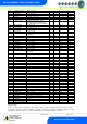
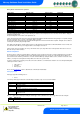
Connecting a 485 legacy module to the controller will govern which set up screens are made available.
Display
Option
485t
485 Network Type
485A
485 Address/Name
gAdd
Show underlying network address assigned to
controller
rLog
Re-log the controller back onto the network
CLrA
Clear the address/name from the controller
ESC
Exit network menu. N.B. this option must be selected to save any changes
made in this menu
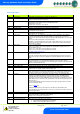
The 485t option shows a value representing the network type. In this controller there is only one type which cannot be changed:
Value
Network Type
1
Genus compatible (all versions)