
User guide


Revision 7.1b Page 12 of 31
Mercury Coldroom Panel Installation Guide
www.resourcedm.com
Warning
Please Note
The specifications of the product detailed on this
Set-Up Guide may change without notice. RDM
Ltd. shall not be liable for errors or for incidental
or consequential damages, directly and indirectly,
in connection with the furnishing, performance or
misuse of this product or document.
Ensure that all power is
switched off before
installing or maintaining
this product
PArA. Set/view parameters (This can be achieved at the network front end)
a. From the function menu scroll to select PArA
b. Pressing Enter while PArA is displayed will enter the parameter menu. The first parameter option will be displayed as P-
01. Pressing the Up or Down button will present the other parameter options P-02, P-03 etc. See the parameter list below
to find what parameter number corresponds to which actual parameter. Pressing the Enter button will show the current
value of the selected parameter. Press Up or Down to modify the value and press Enter again to save the value. The
parameter list number will be displayed again. Two other options are present in the parameter menu – dFLt and ESC.
Selecting ESC will exit setup mode. Selecting dFLt will reset all parameters back to the default values for the current type
of controller.
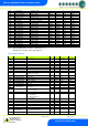
Parameter Table for Compressor/LLV type:
Number
Parameter
Range
o
C (
o
F )
Step
Units
Def. LT
o
C (
o
F )
Def. HT
o
C (
o
F )
P-01
Cut-in Temp
-49.0 to 30.0 (-52.2 to 86)
0.1
Deg
-20 (-4)
0.0 (32)
P-02
Diff
0 to 10 (0 to 10)
0.1
Deg
2 (3.6)
1.5 (2.7)
P-03
Control Weight
0 to 100
1
%
50
50
P-04
Display Weight
0 to 100
1
%
50
50
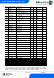
P-85
Key-switch Mode
Not Used
-
-
-
-
P-87
Control Probe type
0 = Use Air on Probe
1 = Use Log Probe
1
0
0
P-90
Resistor Case Off
0 = Disabled. 1 = Enabled
0
0
P-92
Fans temperature mode
0 = Off
1 = Temperature
2 = Over-temperature
3 = Temp/OT
1
0
0
P-93
Fans Off Temperature
-42 to 30 (-52.2 to 86)
0.1
Deg
-10 (14)
8 (46.4)
P-83
Fan Control
0 = Off. 1 = Run. 2 = Pulse
1
P-78
Fan Pulse On
00:00 to 99:00
01:00
mm:ss
P-79
Fan Pulse Off
00:00 to 99:00
01:00
mm:ss
P-98
Control Fail On/Off
00:00 to 10:00
01:00
mm:ss
00:00
00:00
P-29
Probe 3 Operation
( Digital Input )
0 = Plant Fault
1 = External Defrost Input
1
0
0
P-18
Service Time
0 to 128
1
K Hrs
60
60
P-95
Trap Stops LLV/Fans
0 = Off. 1 = Yes
1
0
0
P-99
Load Shedding
0 = No. 1 = Yes
10
0
0
P-35
Display Pin
0 – 999 (0 = off)
1
0
0
P-20
Alarm Delay
00:00 to 99:00
01:00
mm:ss
20:00
20:00
P-21
UT Alarm
-49 to 128 (-56.2 to 262) *
0.1
Deg
-30 (-22)
-2 (28.4)
P-22
OT Alarm
-49 to 128 (-56.2 to 262) *
0.1
Deg
-15 (5)
5 (41)
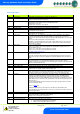
P-23
Log Probe Type
0 = Off. 1 = Logging.
2 = Logging/Alarm
Off
Off
P-24
Slug Log Probe
0 = Off. 1 = On
Off
Off
P-25
Log Alarm Delay
00:00 to 99:00
01:00
mm:ss
20:00
20:00
P-26
Log UT Alarm
-49 to 128 (-56.2 to 262) *
0.1
Deg
-35 (-31)
-1 (30.2)
P-27
Log OT Alarm
-49 to 128 (-56.2 to 262) *
0.1
Deg
-12 (10.4)
6 (42.8)
P-28
Buzzer Mode
0 = Off. 1 = On
On
On
P-40
Defrost Mode
0 = Local. 1 = Remote.
2 = External
Local
Local
P-41
Defrost Start
00:00 to 23:59
00:01
hh:mm
01:00
01:00
P-42
Defrosts per Day
0 to 8
1
6
6
P-43
No Defrost Time
0 to 180
1
hours
12
12
P-44
Def Terminate
-42 to 30 (-43.6 to 86)
0.1
Deg
14 (57.2)
10 (50)
P-45
Def Min Time
00:00 to 99:00
01:00
mm:ss
05:00
05:00
P-46
Def Max Time
00:00 to 99:00
01:00
mm:ss
24:00
24:00
P-47
Drain Down
00:00 to 24:00
00:15
mm:ss
01:30
01:30
P-48
Recovery Time
00:00 to 99:00
01:00
mm:ss
30:00
30:00
P-89
Pump Down Time
00:00 to 99:00
01:00
mm:ss
00:00
00:00
P-86
Fan Delay Mode
0 = Time, 1 = Temp
1
Time
Time
P-49
Fan Delay Time
00:00 to 99:00
01:00
mm:ss
03:00
00:00
P-88
Fan Delay Temp
-42 to 30 (-43.6 to 86)
0.1
Deg
-20 (-4)
0.0 (32)
P-50
Fans In Defrost
0 = Off. 1 = On
1
Off
On
P-91
Defrost Type
0 = Elec. 1 = Elec CIn
1
0
0