PR0150-XXX Mercury Coldroom Panel Installation & User Guide Resource Data Management UK OFFICE Resource Data Management Ltd 80 Johnstone Avenue, Hillington Industrial Estate, Glasgow, Scotland, G52 4NZ, UK +44(0)141 810 2828 sales@resourcedm.com US OFFICE Resource Data Management Inc 100 North Sixth Street, Suite 820C, Minneapolis, MN 55403, USA Tel +1 612 354 2923 Fax +1 612 208 0922 usasales@resourcedm.com www.resourcedm.
Mercury Coldroom Panel Installation Guide Table of Contents: THE MERCURY RANGE ....................................................................................................................................4 Networks .............................................................................................................................................................4 Configuration ....................................................................................................................
Mercury Coldroom Panel Installation Guide REVISION HISTORY........................................................................................................................................ 31 Warning Ensure that all power is switched off before installing or maintaining this product Revision 7.1b Page 3 of 31 www.resourcedm.
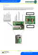
Mercury Coldroom Panel Installation Guide The Mercury Range From Resource Data Management The Mercury Coldroom panel has been specifically developed to suit a variety of coldroom needs. The purpose developed enclosure has a detachable display/keypad for applications where the main enclosure is required to be “out of reach”. The panel is available with or without a main isolator switch. Each internal circuit has either fuse or circuit breaker protection.
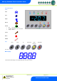
Mercury Coldroom Panel Installation Guide Front Panel Features LED’s: Valve Fans Lights Defrost On-Line Off: No network attached Flashing: Attempting to Log on to network Steady: On-line Service Alarm HACCP Keys Enter Down Up Defrost Now Lights Over-ride Alarm Mute Note: Press and hold the defrost button to force a manual defrost Main Display 4 character blue LED display, used to display temperature and status messages.
Mercury Coldroom Panel Installation Guide Connections Mains Input and Outputs Warning Ensure that all power is switched off before installing or maintaining this product Revision 7.1b Page 6 of 31 www.resourcedm.
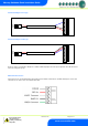
Mercury Coldroom Panel Installation Guide Probe and Alarm inputs Note: When wiring in the probes to the connector, ensure that the 3 wires fitted to the probe connector (not shown on the diagram below) are not moved and remain firmly connected. These wires are used for the external digital inputs; door-open and entrapment. The resistors for the digital inputs are already present on the PCB and therefore external resistors are not required to signal door-open and entrapment alarms.
Mercury Coldroom Panel Installation Guide Internal Cable Diagram for LLV type RED BLACK BLUE Internal Cable Diagram for EEV type RED BLACK BLUE The above cable is used internally to bring the Door Switch and Man-trap inputs to the main processing board. This cable must not be removed or changed in any way, RS485 Network Connection.
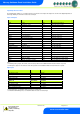
Mercury Coldroom Panel Installation Guide Input/Output Allocation Tables The following tables indicate; on a controller type basis, the functions of the inputs and outputs.
Mercury Coldroom Panel Installation Guide Setting up the Panel Access to the Panel can be achieved by the following methods: Through the front panel keypad Direct access by PC or palm top into the RS232 comms port. This requires a software package (Communicator) available on the RDM website Direct access by PC using Ethernet (IP-L) and an IP browser (e.g. Internet Explorer) Through legacy front end panels on 485 networks Through the RDM Data Manager.
Mercury Coldroom Panel Installation Guide Recommended set-up method If you are not connecting to a network and want to set up the controller through the buttons we recommend you use the following order from the function menu. rtc. Real time clock (This will automatically synchronise on network systems) a. b. c. d. e. f. g. h. i. j. Use the up or down buttons to scroll through the display until the display reads “rtc” Press enter. The display will show “t-1”.
Mercury Coldroom Panel Installation Guide PArA. Set/view parameters (This can be achieved at the network front end) a. From the function menu scroll to select PArA b. Pressing Enter while PArA is displayed will enter the parameter menu. The first parameter option will be displayed as P01. Pressing the Up or Down button will present the other parameter options P-02, P-03 etc. See the parameter list below to find what parameter number corresponds to which actual parameter.
Mercury Coldroom Panel Installation Guide P-94 P-96 P-97 P-80 P-81 P-82 P-60 P-61 P-62 P-63 P-64 P-65 P-66 P-67 P-68 P-69 P-70 P-71 P-72 P-73 P-74 dFLt Defrost Hold Defrost Skip Defrost Skip Time Door alarm dly Door Closes LL Door Stops Fan Lights Mode Sun Lights On Sun Lights Off Mon Lights On Mon Lights Off Tue Lights On Tue Lights Off Wed Lights On Wed Lights Off Thu Lights On Thu Lights Off Fri Lights On Fri Lights Off Sat Lights On Sat Lights Off Restore default values 0 = Off. 1 = On 0 = Off.
Mercury Coldroom Panel Installation Guide P-95 P-99 P-35 P-20 P-21 P-22 P-23 Trap Stops LLV/Fans Load Shedding Display Pin Alarm Delay UT Alarm OT Alarm Log Probe Type P-24 P-25 P-26 P-27 P-28 P-40 Slug Log Probe Log Alarm Delay Log UT Alarm Log OT Alarm Buzzer Mode Defrost Mode P-41 P-42 P-43 P-44 P-45 P-46 P-47 P-48 P-89 P-86 Defrost Start Defrosts per Day No Defrost Time Def Terminate Def Min Time Def Max Time Drain Down Recovery Time Pump Down Time Fan Delay mode P-49 P-88 P-50 P-91 P-94 P-86 P-9
Mercury Coldroom Panel Installation Guide Parameters Description Number P-01 P-02 Parameter Cut-in Temp Diff P-03 Control Weight P-04 P-08 P-09 Display Weight Superheat Ref Response On P-10 Response Off P-11 Control Type P-17 Evap select P-51 EEV Min Opening P-52 Superheat Problem P-53 P-54 P-56 EEV Problem Opening EEV Problem Time EEV Start Opening P-55 Ave Valve Opening P-57 Div Value Description Temperature at which the LLV or compressor will switch on Differential temperature belo
Mercury Coldroom Panel Installation Guide P-93 P-83 Fans Off Temperature Fan Control P-78 P-79 P-77 Fan Pulse On Fan Pulse Off Control Fail Valve P-98 Control Fail On/Off P-29 Probe 1 Operation P-18 Service Time P-95 Trap Stops LLV/Fans P-99 Load Shedding P-35 Display Pin P-20 P-21 P-22 P-23 Alarm Delay UT Alarm OT Alarm Log Probe Type P-24 Slug Log Probe P-25 P-26 P-27 P-28 Log Alarm Delay Log UT Alarm Log OT Alarm Buzzer Mode P-40 Defrost Mode When either P93 is reached or an OT
Mercury Coldroom Panel Installation Guide P-41 P-42 Defrost Start Defrosts per Day P-43 No Defrost Time P-44 Def Terminate P-45 Def Min Time P-46 P-47 P-48 Def Max Time Drain Down Recovery Time P-89 P-86 Pump Down Time Fan Delay mode P-49 P-88 Fan Delay Fan Delay Temp P-50 Fans In Defrost P-91 Defrost Type P-94 Defrost Hold P-96 Defrost Skip P-97 Defrost Skip Time P-80 Door alarm delay P-81 P-82 P-60 Door Closes Valve Door Stops Fan Lights Mode P-61 P-62 P-63 P-64 P-65 P-66 P-67
Mercury Coldroom Panel Installation Guide P-30 Broadcast ID P-31 P-32 P-33 P-34 dFLt Refrigerant Pressure Units Evap Offset Glide Restore default values ID of Plant Controller being used to broadcast Suction Pressure The Broadcast ID is derived from the Rotary Switch positions set on the Plant controller which is providing the remote suction pressure. Note: No two Plant controllers on a local area network can have the same rotary switches positions set. This will have adverse affects on control.
Mercury Coldroom Panel Installation Guide Relay State and functional operation Relay State: Compressor/LLV Relay off Compressor/LLV Relay on Function State Valve on Valve off Wired contact N/C N/C Fans Relay off Fans Relay on Fans on Fans off N/C N/C Lights Relay off Lights Relay on Lights on Lights off N/C N/C Defrost Relay off Defrost Relay on Defrost off Defrost on N/O N/O Alarm Relay off Alarm Relay on Alarm on Alarm off N/C N/C Comments The panel will display Pd (pull-down) just after
Mercury Coldroom Panel Installation Guide The 485A option shows a value representing either the name of the controller in a Genus compatible network. The value shown is of the form 05-6. This means the controller would try to log onto a Genus compatible network using the name ‘RC05-6’. The following options are also available when the network type is set to Genus compatible.
Mercury Coldroom Panel Installation Guide Mask Length 255.255.255.252 255.255.255.248 255.255.255.240 255.255.255.224 255.255.255.192 255.255.255.128 255.255.255.0 30 29 28 27 26 25 24 Mask 255.255.254.0 255.255.252.0 255.255.248.0 255.255.240.0 255.255.224.0 255.255.192.0 255.255.128.0 255.255.0.0 Length 23 22 21 20 19 18 17 16 Mask 255.254.0.0 255.252.0.0 255.248.0.0 255.240.0.0 255.224.0.0 255.192.0.0 255.128.0.0 255.0.0.
Mercury Coldroom Panel Installation Guide O-30 O-32 O-18 S-01 Set Point Offset Timer Run Time Control State -49 to 60 (-56.2 to 140) 0 (Off), 1 (On) 0 to 128 0 (Stabilise), 1 (Normal), 2 (Defrost Min), 3 (Defrost Max), 4 (Drain Down), 5 Fan Delay 6 (Recovery), 7 (OT Alarm), 8 (UT Alarm), 9 (Fans Only), 10 (Lights Only), 11 (Case Off), 12 (Pump_Down), 13 (Df Hold), 14 (Load Shedding) 0.1 Deg 1 K Hrs Step 0.1 0.1 0.1 0.1 0.1 0.1 0.1 0.1 0.1 Units Deg Deg Deg Deg Deg Deg Deg Deg Deg 0.1 Deg 0.1 0.
Mercury Coldroom Panel Installation Guide Switched Resistor Values For PT1000 probes use 820 Ohm switched resistors. For NTC2K and NTC2K25 probes use a 590 Ohm switched resistor. For NTC10K probes use 2k7 Ohm switched resistors. For NTC10K(2) probes use 2k2 Ohm switched resistors. The resistors used must have a tolerance of 1% or better and the resistor must have a power rating of 0.25W. For improved accuracy whilst using switched resistors RDM recommend resistors with 0.1% accuracy are used.
Mercury Coldroom Panel Installation Guide Modifying controller states During normal operation you can change the following states from the function menu Fans Only “FAnS” Selecting the Fans Only option will put the controller into the Fans Only state if the current state is not Fans Only. If the current state is Fans Only then the controller will change to the Normal state. Selecting this option will exit the setup menu automatically.
Mercury Coldroom Panel Installation Guide Specification Power requirements Supply Voltage Range: Supply Frequency: Maximum supply current: Operating temperature range: Operating Humidity: Storage temperature range: Environmental: Size: Weight: Safety: EMC: Ventilation: 100 - 240 Vac ±10% 50 - 60 Hz 40 Amps +50C to +500C 80% maximum -200C to +650C Indoor use at altitudes up to 2000m, Pollution Degree 1, Voltage fluctuations not to exceed ±10% of nominal voltage 240mm (W) x 300mm (H) x 140mm (D) 2.
Mercury Coldroom Panel Installation Guide Lights: Switched Output Voltage: 6A (non inductive) 6A CosФ=0.
Mercury Coldroom Panel Installation Guide Display Remote Mounting The display section of the Coldroom Panel can be removed for remote fixing. Unscrew the two front panel screws; take of the display front and then remove the 4 screws housing the display back onto the main enclosure. The display has a 5 meter cable which requires to be uncoiled from its internal location. Ensure that all power is disconnected before this operation.
Mercury Coldroom Panel Installation Guide Part Numbers Coldroom Coldroom Coldroom Coldroom Coldroom Coldroom Coldroom Coldroom Coldroom Coldroom Coldroom Coldroom Coldroom Coldroom Coldroom Coldroom Variations - EEV, No Isolator, MCB's and No Comms - EEV, Isolator, MCB's and No Comms - EEV, Isolator, MCB's and RS485 Comms - EEV, Isolator, MCB's and IP Comms - LLV, No Isolator, MCB's and No Comms - LLV, No Isolator, MCB's and RS485 Comms - LLV, No Isolator, MCB's and IP Comms - LLV, No Isolator, Fused and
Mercury Coldroom Panel Installation Guide Appendix 1 For later hardware revisions of Coldroom panels the Compressor/LLV and Defrost MCB/Fuse can be interchanged to allow the higher rated MCB/Fuse, 20A, to be used on the Compressor/LLV relay output and the lower rated MCB/Fuse, 10A, to be used on the Defrost relay output. By default the Coldroom panel ships with the 20A MCB/Fuse fitted to the Defrost relay and the 10A MCB/Fuse fitted to the Compressor/LLV.
Mercury Coldroom Panel Installation Guide 7) Remove the fixing plate. Swap the MCB in position “F5 Defrost” to “F1 Compressor/LLSV” and the MCB from “F1 Compressor/LLSV” to “F5 Defrost” taking note of the orientation of the MCB. The image below shows the view of the Coldroom with the fixing plate removed. 8) Ensure the MCB’s are securely fitted and the desired rated MCB’s are in the appropriate positions before re-inserting the fixing plate.
Mercury Coldroom Panel Installation Guide Revision History Revision 1.0 1.1 6.2 Date 03/08/2007 10/08/2007 07/07/2008 6.3 6.3a 6.3b 6.3c 6.3d 6.3e 6.3f 6.3g 31/10/2008 21/05/2009 22/06/2009 26/03/2010 14/04/2010 15/12/2011 15/06/2012 02/07/2012 6.3h 7.0 7.1 7.1a 7.