


Resonant LLC Converter: Operation and Design
6
Application Note AN 2012-09
V1.0 September 2012
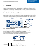
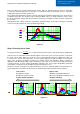
1. At resonant frequency operation, fs=fr.
2. Above resonant frequency operation fs>fr.
3. Below Resonant frequency operation, fs<fr.
Figure 2.4
Despite the aforementioned three modes; which will be explained in details later in this section; the converter
has only two possible operations within the switching cycle, as described below. And each of the modes
pointed out above may contain one or both of these operations.
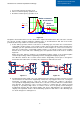
1) Power delivery operation, which occurs twice in a switching cycle; first, when the resonant tank is
excited with a positive voltage, so the current resonates in the positive direction in the first half of the
switching cycle, the equivalent circuit of this mode is shown in Figure 2.5, and second occurance is
when the resonant tank is excited with negative voltage, so the current resonates in the negative
direction in the second half of the switching cycle, the equivalent circuit of this mode is shown in
Figure 2.6.
During the power delivery operations, the magnetizing inductor voltage is the positive/negative
reflected output voltage and the magnetizing current is charging/discharging respectively.
The difference between the resonant current and the magnetizing current passes through the
transformer and rectifier to the secondary side, and power is delivered to the load.
Figure
2
.
5
Figure
2
.
6
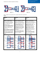
2) Freewheeling operation, which can occurs following the power delivery operation only if the resonant
current reaches the transformer magnetizing current, this only happens when fs<fr, causing the
transformer secondary current to reach zero and the secondary side rectifier to disconnect,
consequently the magnetizing inductor will be free to enter the resonance with the resonant inductor
and capacitor, the frequency of this second resonance is smaller than the original resonant
frequency fr, especially at high values of m where Lm>>Lr, thus the primary current during the
freewheeling operation will only change slightly, and can be approximated to be unchanged for
simplicty. The equivalent circuits of the freewheeling operation in both halves of the switching cycle
are shown in Figure 2.7 and Figure 2.8.
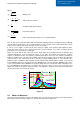
0.1 1 10
0
1
2
3
K .2 m, Fx,( )
K 10 m, Fx,( )
Fx
At resonance
Below resonance
Above
resonance
Cr Lr
Lm
Np
S1
S2
S3
S4
Ns
+
Vo
-
D1
D2
D3
D4
Cr Lr
Lm
Np
S1
S2
S3
S4
Ns
+
Vo
-
D1
D2
D3
D4