


Resonant LLC Converter: Operation and Design
4
Application Note AN 2012-09
V1.0 September 2012
1 Introduction
While a resonant LLC converter has several desired features such as high efficiency, low EMI and high
power density, the design of a resonant converter is an involved task, and requires more effort for
optimization compared to PWM converters. This document aims to simplify this task, and make it easier to
optimally design the resonant tank. This document provides an overview of LLC converter operation and
design guidelines. Finally, a comprehensive design example is given along with schematics, bill of materials,
experimental results and waveforms.
2 Overview of LLC Resonant Converter
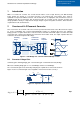
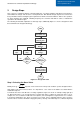
This section offers an overview of the LLC converter operation and waveforms in the different modes. Figure
2.1 shows a Full-Bridge LLC converter with Full-Bridge rectifier. In a simplistic discussion, the switching
bridge generates a square waveform to excite the LLC resonant tank, which will output a resonant sinusoidal
current that gets scaled and rectified by the transformer and rectifier circuit, the output capacitor filters the
rectified ac current and outputs a DC voltage.
Figure 2.1 Full-Bridge LLC converter with Full-Bridge rectifier
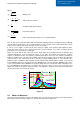
2.1 Converter Voltage Gain
Converter gain= switching bridge gain * resonant tank gain * transformer turn ratio (Ns/Np)
Where the switching bridge gain is 1 for a Full-Bridge and 0.5 for a Half-Bridge.
The resonant tank gain can be derived by analyzing the equivalent resonant circuit shown in
Figure 2.2, the resonant tank gain is the magnitude of its transfer function as in Eq. 1.
Figure 2.2 Equivalent resonant circuit
2
2
2
2
2
2
2
2
_
_
111
1
)(
)(
),,(
QmFFxFm
mF
sV
sV
FmQK
xx
x
acin
aco
x
Eq. 1
Switching
bridge
LLC tank
Transformer
and Rectifier
Output
Capacitor
Cr
Lr
Lm
Np
S1
S2
S3
S4
Ns
D1
D2
D3
D4
+
Vsw
-
+
Vo
-
RoCo
Cr
Lr
Lm
Vo_ac
Rac
Vin_ac