

Resonant LLC Converter: Operation and Design
15
Application Note AN 2012-09
V1.0 September 2012
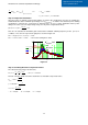
5.3 Experimental Waveforms and Efficiency
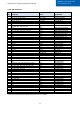
The design example was implemented with the specification shown in Table 5
Table 5 Prototype specifications
Resonant frequency
݂
110 kHz
Minimum switching frequency
݂
௦
_
50 kHz
Resonant capacitor
ܥ
0.94 µF
Transformer Specifications
Turns ratio
ܰ
:
ܰ
௦
1:12
Leakage (Resonant) inductor
ܮ
2.2 µH
Magnetizing inductor
ܮ
12.2 µH
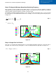
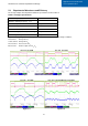
Figure 5.3 through Figure 5.6 shows experimental waveforms at different input voltage conditions,
Red channel: Primary FET V
gs
Yellow channel: Primary FET V
ds
Green channel: Resonant current I
Lr
Blue channel: Rectifier output current I
D1
+I
D3
Vin= 33V Po=250W Vin= 18V Po=125W
Figure 5.3 Figure 5.4
Vin= 36V Po=250W Vin= 36V Light Load Missing Cycle Mode
Figure 5.5 Figure 5.6