

Resonant LLC Converter: Operation and Design
14
Application Note AN 2012-09
V1.0 September 2012
݀
݀ܨ
ܭ
(
ܳ
௫
, ݉, ܨ
)
ฬ
ொ
ೌೣ
ୀ.ସ, ୀ.ଷ
= 0 → ܨ
= 0.489
→ ݂
௦_
= ܨ
∙ ݂
= 48.9݇ܪݖ
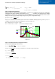
Step 4: Voltage Gain Verification
Since the power is derated at lower input voltages as listed in the specifications, we have to calculate the
maximum Q value at the minimum input voltage case (ܳ
௫@
), as follows. Note that this power derating
specification is related to the solar panel I-V characterestics. (In case of other applications where power
rating is the same across the input voltage range, we only have a single Qmax value).
ܳ
௫@
= ܳ
௫
∙
ܸ
_
ܸ
_ ௫
= 0.2
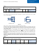
Then we can calculate the maximum gain reached at the minimum switching frequency for the ܳ
௫@
condition, or we can look it up from the gain plot as shown in Figure 5.2.
ܭ
௫
= ܭ
(
ܳ
௫@
, ݉, ܨ
)
= 1.974
ܭ
௫
= 1.974 > ܯ
௫
= 1.833 → No need for tuning the m value
Figure
5
.
2
Step 5: Calculating Resonant Components Values
The reflected load resistance at full load is,
ܴ
_
=
8
ߨ
ଶ
∙ ൬
ܰ
ܰ
௦
൰
ଶ
ܸ
௨௧
ଶ
ܲ
, ௫
→ ܴ
_
= 3.534 Ω
Next we solve the equations below to obtain the resonant tank components values
ܳ
௫
= 0.4 =
ඥ
ܮ
/ܥ
3.534 Ω
݂
= 100݇ܪݖ=
1
2ߨ
ඥ
ܮ
∙ ܥ
݉ = 6.3 =
ܮ
+ ܮ
ܮ
∴ ܮ
= 2.25ߤܪܮ
= 11.93ߤܪܥ
= 1.13ߤܨ
0.489
0.1 1 10
0
1
2
3
K .2 m Fx( )
K .3 m Fx( )
K .4 m Fx( )
Fx
1.974
Q
max
=0.4
Q
max@Vmin
=0.2