

Resonant LLC Converter: Operation and Design
13
Application Note AN 2012-09
V1.0 September 2012
5 Design Example
5.1 Application and Specifications
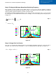
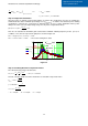
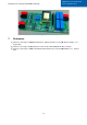
Our design example is applicable to the dc-dc stage of a solar micro inverter, as shown in Figure 5.1, with
specifications as listed in Table 4. According to the discussion in section 4, the LLC converter will be
implemented with a full-bridge on the primary side and a full-bridge rectifier on the secondary side, same
circuit as shown in Figure 2.1.
Figure
5
.
1
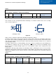
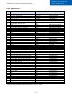
Table 4 Specifications
Output voltage 400V
Input voltage 18V – 36V (33V nominal)
Output power 250W
Output power derates linearly with input voltage
Ex: Output power= 125W @ Vin=18V
Resonant frequency 100kHz
5.2 Design Steps
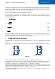
We start the design by calculating the transformer turn ratio and the minimum and maximum voltage gains of
the resonant tank, as follows.
ܯ
= 1
ܰ
ܰ
௦
=
ܸ
_
ܸ
௨௧
∙ ܯ
→
ܰ
ܰ
௦
= 0.0825
ܯ
௫
=
ܸ
_
ܸ
_
∙ ܯ
→ ܯ
௫
= 1.833
ܯ
=
ܸ
_
ܸ
_ ௫
∙ ܯ
→ ܯ
= 0.917
Next, we follow the design steps discussed in section 3, as follows.
Step 1: Selecting the Qmax Value
Let’s choose ܳ
௫
= 0.4
Step 2: Selecting the m Value
Let’s choose ݉ = 6.3
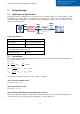
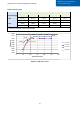
Step 3: Finding the Minimum Normalized Switching Frequency
We can solve the gain equation to find the minimum frequency, which occurs at the peak of the Qmax curve,
as shown below, or we can look it up from the gain plot as shown in Figure 5.2.
DC-DC
Converter
DC Link
~30V
400V
240Vac
60Hz
DC-AC
Inverter