

Resonant LLC Converter: Operation and Design
12
Application Note AN 2012-09
V1.0 September 2012
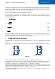
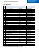
Table 2
Primary Bridge - Half-Bridge compared to Full-Bridge
I
rms
I
rms
2
Number of FETs Total FETs conduction
losses
N
p
R
pri
Transformer primary
copper loss
× 2 × 4 ÷ 2 × 2 ÷ 2 ÷ 2 × 2
*Comparison assumes same FET and same transformer core
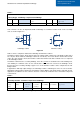
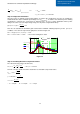
LLC converters can also be implemented with a full-bridge or a full-wave rectifier circuit on the secondary
side, as shown in Figure 4.2
Full-bridge rectifier Full-wave rectifier
Figure
4
.
2
Table 3 shows a comparison between the full-bridge and full-wave rectifiers.
A full-wave rectifier requires diodes that are twice the voltage rating compared to a full-bridge rectifier, but it
has only two diodes while the full-bridge rectifier has four diodes, since each diode in both rectifier circuits
carries the same average current, the full-wave rectifier has half the total diode conduction losses compared
to the full-bridge rectifier.
A full-wave rectifier has two secondary windings, hence the resistance is doubled for the same winding area,
each winding in a full-wave caries an rms current that is
√
0.5 of the rms current of the full-bridge circuit,
therefore the total secondary windings copper losses of the full-wave rectifier is twice compared to the full-
bridge rectifier.
In applications with high output voltages, the full bridge rectifier is advantageous since we can use diodes
with half the voltage rating compared to the full-wave rectifier. While in low output voltages and high currents
application, the full-wave is more common, because of lower total conduction losses and lower component
count and cost.
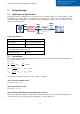
Table 3
Secondary Rectifier - Full-Wave compared to Full-Bridge
Diode
voltage
rating
Number of
diodes
Diode
conduction
losses
Number of
secondary
windings
R
sec
per winding
I
rms
per winding
Transformer secondary
copper loss
× 2 ÷ 2 ÷ 2 × 2 × 2 ×
√
0
.
5
× 2
*Comparison assumes same diode voltage drop and same transformer core
Np
Ns
D1
D2
D3
D4
+
Vo
-
Co
Np
+
Vo
-
D2
D1
Ns
Ns