


Resonant LLC Converter: Operation and Design
11
Application Note AN 2012-09
V1.0 September 2012
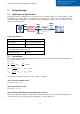
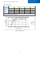
Few iterations are needed in order to reach the optimized design, as shown in the design flow chart in Figure
3.1. If K
max
is not enough, then we have to reduce the m value and repeat steps 3 and 4, in order to gain a
higher boost gain. On the other side, If K
max
is higher than what is required; in that case we can increase the
m value and repeat steps 3 and 4 in order to gain a better efficiency.
Step 5: Calculating Resonant Components Values
After few iterations of the design flow and reaching the optimum m value, we can proceed to calculating the
resonant tank components values, Eq. 4 and Eq. 5 can be solved to find L
r
and C
r
, and then L
m
can be
calculated using Eq. 6.
max
2
2
2
2
min,
8
o
o
S
P
ac
P
V
N
N
R
min,
max
ac
rr
R
CL
Q
Eq. 4
rr
r
CL
f
2
1
Eq. 5
r
mr
L
LL
m
Eq. 6
It must be noted that selection of the resonant frequency f
r
was not considered in the design steps above,
since it has no impact on the maximum gain and operation region of the resonant converter, however it is
selected considering the converter power density and power losses.
4 Bridge and Rectifier Selection
An important step to achieve the best converter performance is to choose the right bridge and rectifier
circuits.
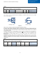
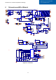
LLC converters can be implemented with a full-bridge or a half-bridge circuit on the primary side, as shown in
Figure 4.1,
Full-bridge switching circuit Half-bridge switching circuit
Figure
4
.
1
Table 2 shows a comparison between the half-bridge and the full-bridge switching circuits.
A half-bridge would have twice the current of what a full-bridge would have, the squared rms current in the
half-bridge case is four times, the number of switches in a half bridge is half of that in a full-bridge, therefore,
the total FETs conduction losses of a half-bridge is twice compared to the full-bridge.
Although a half-bridge requires half the primary number of turns for the same voltage gain and magnetic flux
swing, thus half the primary winding resistance, the primary copper losses are still twice compared to the full-
bridge because the squared rms current in the half-bridge case is four times.
So in applications with high primary currents, where conduction losses are dominant, it is suggested to use a
full-bridge switching circuit.
S1
S2
S3
S4
S1
S2
C1
C2