

Resonant LLC Converter: Operation and Design
10
Application Note AN 2012-09
V1.0 September 2012
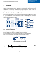
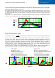
Step 3: Finding the Minimum Normalized Switching Frequency
After selecting a value for Qmax and an initial value for m, we need to find the minimum normalized
switching frequency that will guarantee inductive operation for the Qmax (max load) condition, this minimum
frequency will also guarantee inductive operation for all other loads.
The minimum normalized switching frequency occurs at the peak gain of the Qmax curve, so it can be found
by solving Eq. 2 (assumed Qmax=0.4 and m=6 as an example), or can be visually spotted in the gain plot as
in Figure 3.4.
0),,(
6,4.0max
min
mQ
FxmQK
dFx
d
Eq. 2
Solve for
min
Fx
Figure 3.4
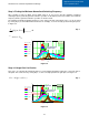
Step 4: Voltage Gain Verification
This step is to verify that the maximum gain K
max
reached during maximum load by the selected m value is
adequate. This can be done by solving Eq. 3, or can be visually spotted in the gain plot as in Figure 3.4.
),,(
minmaxmax
FxmQKK
Eq. 3
Figure 3.5
0.1 1 10
0
1
2
3
K .2 m, Fx,
(
)
K .25 m, Fx,
(
)
K .3 m, Fx,
(
)
K .4 m, Fx,
(
)
K .6 m, Fx,
(
)
K 5 m, Fx,
(
)
Fx
Max load curve
(Qmax=0.4)
Light load
m=6
Fx
min
0.1 1 10
0
1
2
3
K .2 m Fx( )
K .25 m Fx( )
K .3 m Fx( )
K .4 m Fx( )
K .6 m Fx( )
K 5 m Fx( )
Fx
Max load curve
(Qmax=0.4)
Light load
m=6
Fx
min
K
max