
Product Overview
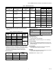
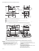

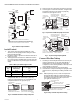
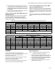
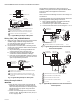
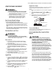
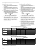
Table Of Contents

V800 COMBINATION GAS CONTROLS FOR HEATING APPLIANCES
60-2019—09 6
Fig. 4. Sediment Trap Installation.
Install Control
1. This control can be mounted 0-90 degrees, in any
direction, from the upright position of the gas control
knob, including vertically.
2. Mount the control so gas flow is in direction of arrow on
bottom of control.
3. Thread pipe the amount shown in Table 6 for insertion
into control. DO NOT THREAD PIPE TOO FAR. Valve dis-
tortion or malfunction may result if pipe is inserted too
deeply.
Table 3. NPT Pipe Thread Length in inches.
4. Apply a moderate amount of good quality pipe
compound (DO NOT use Teflon tape) to pipe only,
leaving two end threads bare. On LP installations, use
compound resistant to LP gas (See Fig. 5).
Fig. 5. Use Moderate Amount of Pipe Compound.
5. Remove seals over control inlet and outlet, if necessary.
6. Connect pipe to control inlet and outlet. To tighten inlet
and outlet connections, use wrench on projecting
wrench boss (See Figures 6 and 7).
Fig. 6. Top View of Standard Capacity Gas Control.
Fig. 7. Top View of High Capacity Model.
Connect Pilot Gas Tubing
1. Cut tubing to desired length and bend as necessary for
routing to pilot burner. Do not make sharp bends or
deform tubing. Do not bend tubing at control after
compression nut has been tightened, as this may result
in gas leakage at connection.
2. Square off and remove burrs from end of tubing.
3. Unscrew brass compression fitting from pilot gas outlet
(Figures 6 and 7). Slip fitting over tubing and slide out of
way.
NOTE: When replacing a control, cut off old compression
fitting and replace with new compression fitting
provided on new combination gas control. Never use
old compression fitting as it may not provide a
gas-tight seal. Refer to Fig. 8.
Fig. 8. Always use New Compression Fitting.
Pipe Size
(in.)
Thread Pipe this
Amount (in.)
Maximum Depth Pipe can
be Inserted Into Control
(in.)
3/8 9/16 3/8
1/2 3/4 1/2
3/4 13/16 3/4
GAS
CONTROL
GAS
CONTROL
HORIZONTAL
DROP
PIPED
GAS
SUPPLY
PIPED
GAS
SUPPLY
3 IN.
(76 MM)
MINIMUM
3 IN.
(76 MM)
MINIMUM
RISER
GAS
CONTROL
TUBING
GAS
SUPPLY
HORIZONTAL
DROP
3 IN.
(76 MM)
MINIMUM
RISER
M3077A
2
1
2
2
1
2
ALL BENDS IN METALLIC TUBING SHOULD BE SMOOTH.
CAUTION: SHUT OFF THE MAIN GAS SUPPLY BEFORE REMOVING
END CAP TO PREVENT GAS FROM FILLING THE WORK AREA. TEST
FOR GAS LEAKAGE WHEN INSTALLATION IS COMPLETE.
TWO IMPERFECT
THREADS
GAS CONTROL
THREAD PIPE THE AMOUNT
SHOWN IN TABLE FOR
INSERTION INTO GAS CONTROL
APPLY A MODERATE AMOUNT OF
PIPE COMPOUND TO PIPE ONLY
(LEAVE TWO END THREADS BARE).
M3075B
PIPE
ON
OFF
PILOT
INLET
GAS
INLET
PILOTSTAT
POWER UNIT
PILOT FLOW ADJ. SCREW
(BENEATH COVER SCREW)
M23296
PILOT GAS OUTLET
PRESSURE TAPPING
DIRECTLY BENEATH
STEP-OPENING
REGULATOR (“C” MODEL)
WRENCH
BOSS
PRESSURE REGULATOR
ADJUSTMENT (BENEATH
COVER SCREW)
MANUAL GAS
CONTROL KNOB
STANDARD
PRESSURE
REGULATOR
(“A” MODEL)
INSTALL LONG
SCREW IN
OUTSIDE CORNER
TH
TR
TH
TR
M23297
STEP-OPENING
REGULATOR
(“C” MODEL)
PRESSURE REGULATOR
ADJUSTMENT (BENEATH
COVER SCREW)
INSTALL LONG
SCREW IN
OUTSIDE CORNER
TH
TR
TH
TR
ON
OFF
PILOT
WRENCH
BOSS
MANUAL GAS
CONTROL KNOB
PILOTSTAT
POWER UNIT
PILOT FLOW ADJ. SCREW
(BENEATH COVER SCREW)
PILOT GAS OUTLET
PRESSURE TAPPING
DIRECTLY BENEATH
STANDARD
PRESSURE
REGULATOR
(“A” MODEL)
GAS
INLET
GAS CONTROL BODY
(INLET END)
TIGHTEN NUT ONE TURN
BEYOND FINGER-TIGHT
TO PILOT
BURNER
FITTING BREAKS OFF AND CLINCHES
TUBING AS NUT IS TIGHTENED
M23298